
Intelligent drop switch

A drop switch, intelligent technology, applied in the direction of electric switches, air switch parts, electrical components, etc., can solve problems such as hindering maintenance and repair time, screw rusting and jamming, people's life and property safety loss, etc., to achieve safe and reliable protection performance, avoid burning accidents, and prevent outdoor corrosion

Pending Publication Date: 2021-06-25
江西广润电气有限公司
View PDF1 Cites 0 Cited by
  • Summary
  • Abstract
  • Description
  • Claims
  • Application Information

AI Technical Summary

Problems solved by technology

[0002] The components of the 10KV isolating switch currently used in the market are exposed outdoors, and the cable inlet and outlet sides are also exposed outdoors. The product structure is in a low-end state. After one year of operation, the screws began to rust, and the knife switch was opened. Finally, the gate will not be closed, and the screws fastening the blades will be rusted and stuck, seriously affecting the safe and reliable operation of the power grid, hindering the time for maintenance and emergency repairs, and causing great losses to people's lives and property safety.
[0003] Such as CN204966368U, open date: 2016-01-13, discloses a kind of novel GW9 isolating switch, is made up of three same conjoined single poles arranged on the same base, each single pole is composed of an operating mechanism, a transmission mechanism , knife switch mechanism and conductive mechanism, each mechanism in the single pole is exposed outdoors, easy to rust

Method used


Image

  • Intelligent drop switch
  • Intelligent drop switch
  • Intelligent drop switch

Examples


Embodiment Construction

[0026] In order to make the purpose, technical solutions and advantages of the embodiments of the present invention more clear, the technical solutions in the embodiments of the present invention will be clearly and completely described below in conjunction with the drawings in the embodiments of the present invention.

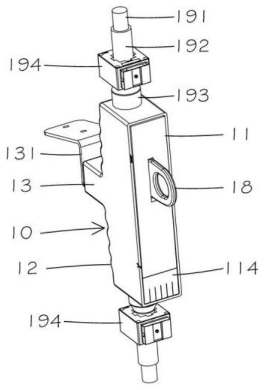
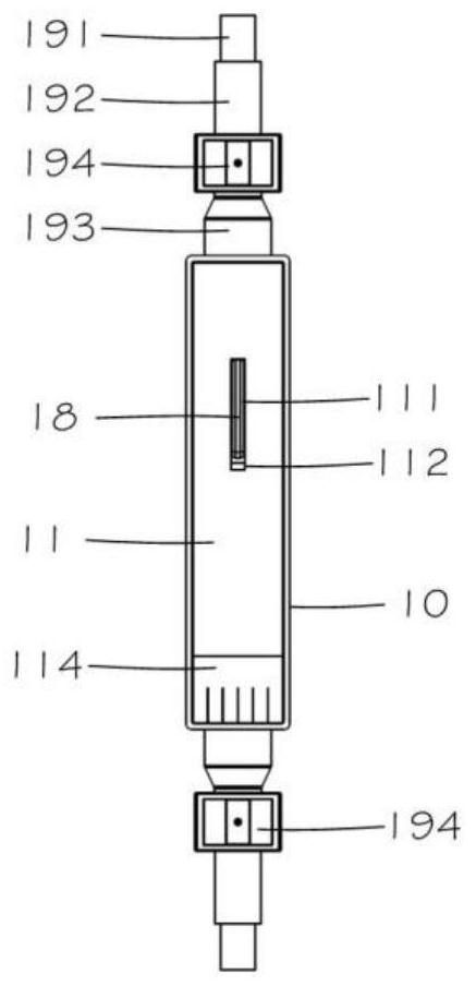
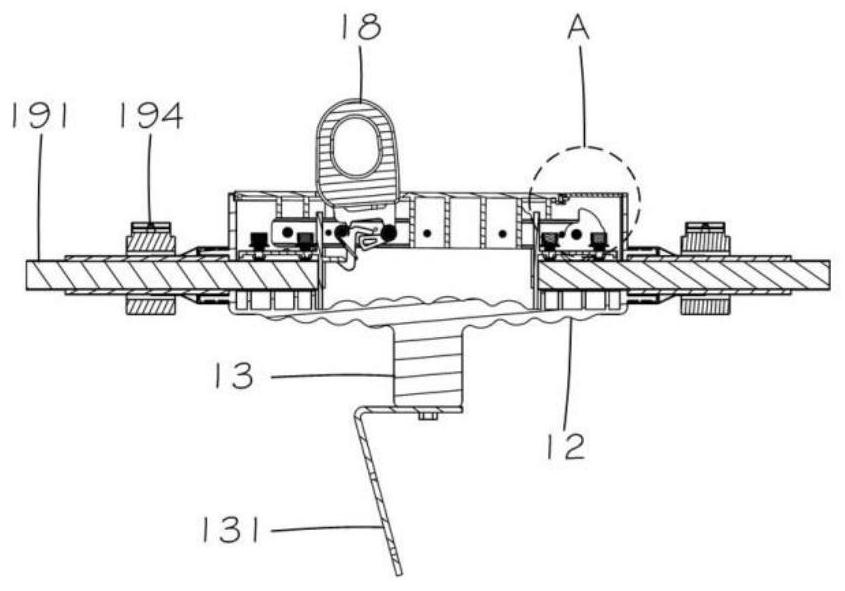
[0027] like Figure 1 to Figure 9 The smart drop switch of the present invention shown includes a box frame 10, the box frame 10 includes a box cover 11, a bottom plate 12 and a shaft joint 13, and the shaft joint 13 is fixedly installed on a mounting plate 131, and the box body The frame 10 is made of SMC resin, which has a good insulating effect.

[0028] Left knife rest 14 and right knife rest 15 are installed respectively on the both sides of box frame 10, and right knife rest 15 is provided with hinged part 151, and conductive blade 16 is rotatably installed on hinged part 151, and conductive blade 16 comprises first The conductive blade 161 and the seco...


PUM


Abstract

The invention discloses an intelligent drop switch, which comprises a box body frame, wherein the box body frame comprises a box cover, a bottom plate and a shaft joint, two sides of the box body frame are respectively provided with a left tool apron and a right tool apron, the right tool apron is rotatably provided with conductive blades, the conductive blades are connected through a bolt and a pinhole bolt, the conductive blade is provided with a first pin shaft and a second pin shaft, the first pin shaft is rotatably provided with a rotating hook plate, the rotating hook plate comprises a first hook part and a second hook part, the second pin shaft is rotatably provided with a pulling and buckling plate, the pulling and buckling plate comprises a locking part and an outer hook part, the left tool apron is provided with a fixing plate, the first hook part is buckled with the fixing plate, and the second hook part is buckled with the locking part. The intelligent drop switch is reasonable in structure and easy to manufacture. The closed design is adopted, a disconnecting switch performs opening and closing operation, and all elements are sealed in a box, so that the elements and cables are prevented from being exposed in outdoor air, water, ice and sand can be effectively prevented, outdoor corrosion is completely eradicated, and the safety and reliability of equipment are protected.

Description

technical field [0001] The invention relates to the technical field of an isolating switch, in particular to an intelligent drop switch. Background technique [0002] The components of the 10KV isolating switch currently used in the market are exposed outdoors, and the cable inlet and outlet sides are also exposed outdoors. The product structure is in a low-end state. After one year of operation, the screws began to rust, and the knife switch was opened. Finally, the gate cannot be closed, and the screws fastened by the blades are rusted and stuck, seriously affecting the safe and reliable operation of the power grid, hindering the time for maintenance and emergency repairs, and causing great losses to people's lives and property safety. [0003] Such as CN204966368U, open date: 2016-01-13, discloses a kind of novel GW9 isolating switch, is made up of three same conjoined single poles arranged on the same base, each single pole is composed of an operating mechanism, a transm...

Claims


Application Information

Patent Timeline
Patent Type & Authority Applications(China)
IPC IPC(8): H01H9/04H01H31/02
CPCH01H9/04H01H31/02
Inventor 马云涌
Owner 江西广润电气有限公司
Learn More