Double-control circuit of intelligent switch and mechanical switch
A technology of mechanical switch and intelligent switch, which is applied in the direction of circuit, electric switch, energy-saving control technology, etc., can solve the problems of being unusable, no longer having dual control functions, increasing the cost of intelligent home renovation, etc., achieving low cost and beneficial Promote and popularize, reduce the effect of transformation difficulty and cost
- Summary
- Abstract
- Description
- Claims
- Application Information
AI Technical Summary
Problems solved by technology
Method used
Image
Examples
Embodiment 1
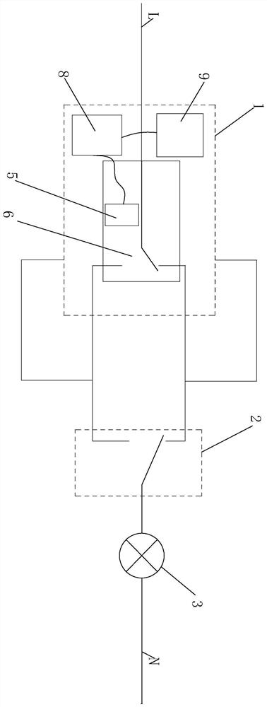
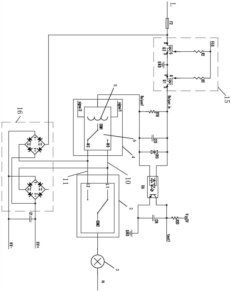
[0027] Embodiment one, such as Figure 1 to Figure 2 As shown, a dual control circuit of an intelligent switch and a mechanical switch includes a rectifier bridge voltage conversion sub-circuit 15, a field effect tube voltage conversion sub-circuit 16, a first wire 10, a second wire 11, an intelligent switch 1, and a mechanical switch 2 , a controlled device 3 and a current detection subcircuit for detecting the working state of the controlled device, the intelligent switch 1, the mechanical switch 2 and the controlled device 3 are sequentially connected in series, and the field effect tube voltage conversion subcircuit 16 is electrically The input terminal of the rectifier bridge voltage conversion sub-circuit 15 is connected to the live wire, and the rectifier bridge voltage conversion sub-circuit 15 is electrically connected between the mechanical switch and the smart switch 1. Between, the smart switch 1 includes a main control unit 8, a wireless signal processing unit 9 a...
Embodiment 2
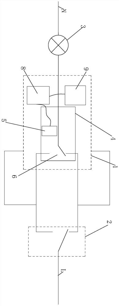
[0042] Embodiment two, such as image 3 As shown, the second embodiment is similar to the first embodiment, the only difference is that: the mechanical switch 2, the smart switch 1 and the controlled device 3 are connected in series sequentially, and the second common connection port COM2 is connected to the mains The first common connection port COM1 is connected to the controlled device 3, and the controlled device 3 is connected to the neutral line L in the mains. The working principle of the second embodiment is similar to that of the first embodiment, and will not be described in detail here.
PUM
 Abstract
Description
Claims
Application Information
 - R&D
- Intellectual Property
- Life Sciences
- Materials
- Tech Scout
- Unparalleled Data Quality
- Higher Quality Content
- 60% Fewer Hallucinations
Browse by: Latest US Patents, China's latest patents, Technical Efficacy Thesaurus, Application Domain, Technology Topic, Popular Technical Reports.
© 2025 PatSnap. All rights reserved.Legal|Privacy policy|Modern Slavery Act Transparency Statement|Sitemap|About US| Contact US: help@patsnap.com


