
Electric power engineering cable effective deicing device convenient to advancing

A technology for electric power engineering and cables, applied in the field of effective deicing devices for electric power engineering cables, can solve problems such as broken cables, slow movement of deicing devices, electric shocks, etc., to prevent slipping or standing still, and prolong scraping time, simple and convenient operation

Inactive Publication Date: 2021-06-25
李园
View PDF0 Cites 0 Cited by
  • Summary
  • Abstract
  • Description
  • Claims
  • Application Information

AI Technical Summary

Problems solved by technology

When it snows in winter, the cable will gather a lot of snow, because the cold weather will cause a lot of ice cubes to form on the cable over time, which will increase the weight of the cable, and will cause the cable to break over time, not only causing Large-scale power outages will also cause electric shock problems when pedestrians walk past the grounding of the cable
Most of the existing cable deicing devices are hanging deicing devices. When cleaning the ice on the cable, the deicing device is hung on the cable, and the guide wheel is driven to rotate by driving the motor. Thereby realizing the purpose of removing ice cubes through the deicing mechanism while the device moves forward automatically along the cable, but the deicing device can only eliminate the large ice cubes on the cable, so that on the cable after removal There will still be some sticking fine ice chips, so the guide wheels on the deicing device will slip when moving forward, which will cause the deicing device to move forward slowly or cannot continue to move forward along the cable. Seriously Affect the efficiency of cable deicing

Method used


Image

  • Electric power engineering cable effective deicing device convenient to advancing
  • Electric power engineering cable effective deicing device convenient to advancing
  • Electric power engineering cable effective deicing device convenient to advancing

Examples


Embodiment Construction

[0019] Below in conjunction with accompanying drawing and specific embodiment the present invention is described in further detail:

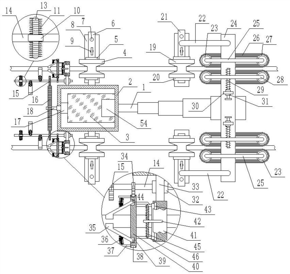
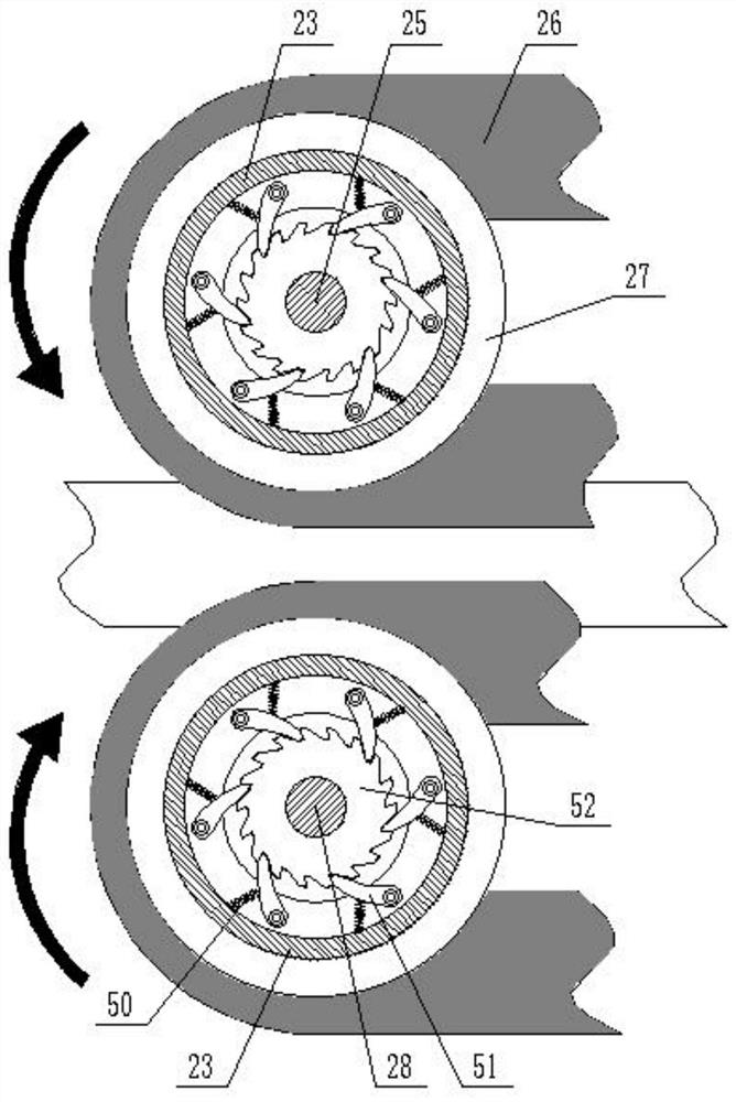
[0020] Such as figure 1 , figure 2 , image 3 , Figure 4 , Figure 5As shown, an effective deicing device for power engineering cables that is convenient to advance includes an electric telescopic rod 1, one end of the elongated end of the electric telescopic rod 1 is fixedly connected to a box body 2, and the top surface of the box body 2 is hinged A box door 53 is provided, a counterweight 3 is fixedly connected inside the box 2, a battery 54 is fixedly arranged on the top surface of the counterweight 3, and the box 2 on one side of the counterweight 3 is fixedly connected There is a motor 17, the output end of the motor 17 extends out of the box body 2 and is connected to it for rotation. One end of the output end of the motor 17 outside the box body 2 is fixedly connected to a rotating rod 18, and the rotating rod 18 is covered There ...


PUM


Abstract

The invention discloses an electric power engineering cable effective deicing device convenient to advancing. The device comprises an electric telescopic rod, one end of the extension end of the electric telescopic rod is fixedly connected with a box body, a box door is hinged to the top surface of the box body, a balancing weight is fixedly connected into the box body, and a battery is fixedly arranged on the top surface of the balancing weight. The electric telescopic rod is repeatedly stretched and shortened, so that the device intermittently advances forwards; and meanwhile, the deicing structure synchronously intermittently moves forwards, and the device intermittently advances, so that not only is the normal advancing of the device ensured, the situation that the device retreats is avoided, but also the time for scraping ice and snow on a local cable is effectively prolonged, ice chips on the cable are cleared away more thoroughly, the device is effectively prevented from slipping or moving still, the device can continuously and stably move forwards, ice pitons and the ice chips on the cable are well cleared away, and meanwhile operation is easy and convenient.

Description

technical field [0001] The invention relates to the field of electric power engineering, in particular to an effective deicing device for electric power engineering cables that is convenient to advance. Background technique [0002] Cables are one of the essential power transmission equipment in the power industry. Usually, cables are used to transmit electric energy thousands of miles away to thousands of households, so as to achieve the purpose of power transmission. In order to prevent electric shock damage caused by cables to the human body, most cables are laid at high altitude through utility poles. When it snows in winter, the cable will gather a lot of snow, because the cold weather will cause a lot of ice cubes to form on the cable over time, which will increase the weight of the cable, and will cause the cable to break over time, not only causing Large-scale power outages will also cause electric shock problems when pedestrians walk near the grounding of the cable...

Claims


Application Information

Patent Timeline
Patent Type & Authority Applications(China)
IPC IPC(8): H02G7/16
CPCH02G7/16
Inventor 李园
Owner 李园
Learn More