Supercharge Your Innovation With Domain-Expert AI Agents!

Method for composite flow molding

A molded, actuated technology applied in the direction of coating etc.

Pending Publication Date: 2021-06-25
ARRIS COMPOSITES INC
View PDF2 Cites 1 Cited by
  • Summary
  • Abstract
  • Description
  • Claims
  • Application Information

AI Technical Summary

Problems solved by technology

However, using such processes to manufacture complex parts with very small, thin or intricately detailed features, especially those requiring considerable strength and stiffness, presents many challenges

Method used


Image

  • Method for composite flow molding
  • Method for composite flow molding
  • Method for composite flow molding

Examples


Embodiment Construction

[0144] The following terms and its deformation form are defined below for use in the present disclosure and the appended claims:

[0145] "Axial or axial alignment" means, for example, in the background of the plunger or plunger chamber, and in the background of the plunger, and in the background of the mold cavity, representing the long (maximum) axis of the mold cavity Or spindle alignment.

[0146] • "Transverse or lateral alignment" means, for example, in the background of the plunger or plunger chamber, in the background of the plunger, and in the background of the mold cavity, with respect to the long in the plane (most Length) The axis of the spin of 90 degrees is aligned.

[0147] · "Plane" means, for example, an axis that is rotationally exiting the plane of the plane from the main surface of the mold chamber in the context of the mold cavity. In an embodiment of the invention, the stroke axis of the plunger is outside the plane relative to the main surface of the mold ch...


PUM


Abstract

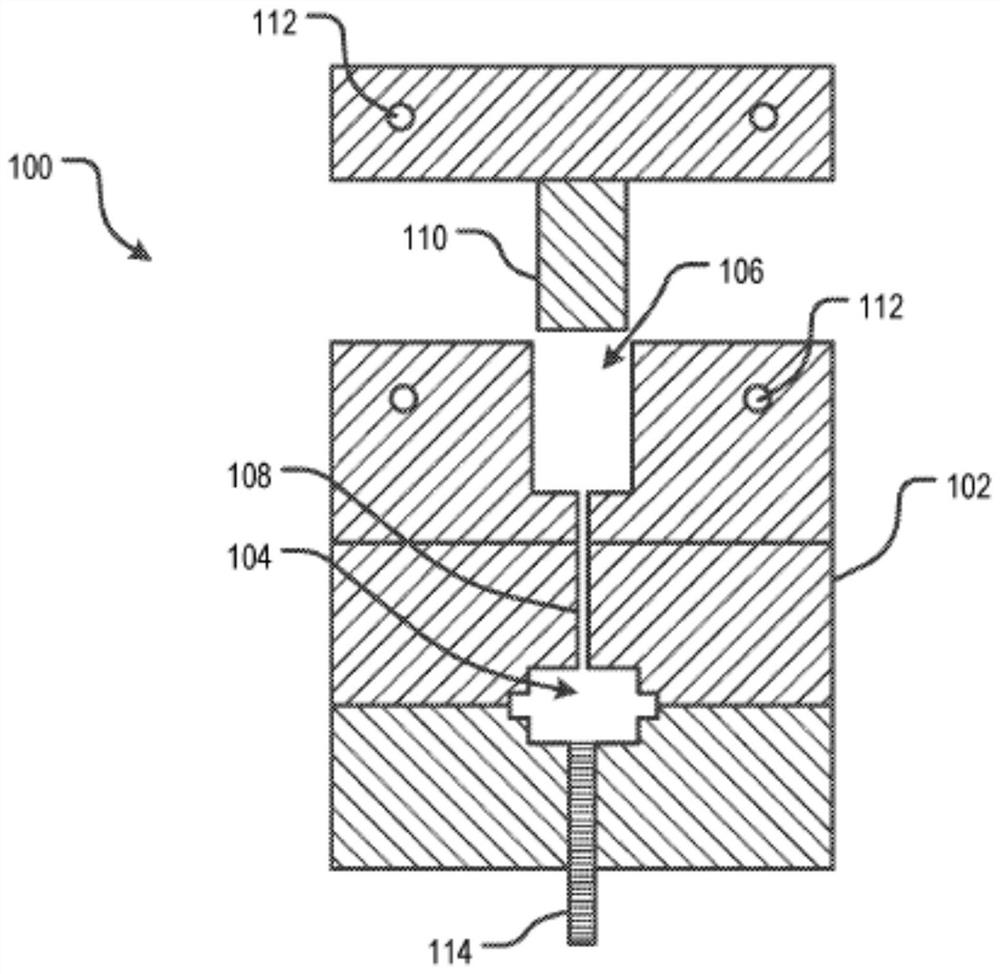
An apparatus for molding a part includes a plunger cavity, a plunger, and a mold cavity, wherein the plunger is oriented out-of-plane with respect to a major surface of the mold cavity, and first and second vents couples to respective first and second portions of the mold cavity. In a method, resin and fiber are forced into the mold cavity from a plunger cavity, and at least some of the fibers and resin are preferentially flowed to certain region in the mold cavity via the use of vents.

Description

[0001] Related case statement [0002] This case requires the priority of U.S. Patent Application No. Sn 62 / 743, 390, filed on October 9, 2018, which is incorporated herein by reference. Technical field [0003] The present disclosure generally involves molding complex parts, especially those with very characteristic, thin or complex and fine. Background technique [0004] It is generally desirable to manufacture parts from fiber composites. The fiber composite parts include fibers dispersed within a matrix formed of the resin. In addition to preventing fiber wear and environmental erosion, the substrate is also surrounding and supporting the fibers by maintaining the relative position of the fibers. The fibers give them mechanical and physical properties to enhance the mechanical and physical properties of the matrix. This combination is synergistic; the composite material has a material properties that cannot be provided, such as very high strength-weight ratio. [0005] A varie...

Claims


Application Information

Patent Timeline
IPC IPC(8): B29C45/00B29C45/02B29C45/34B29C45/53B29C45/63B29C33/10B29C43/34B29C43/36B29C33/00B29K105/12
CPCB29C33/0061B29C33/10B29C43/34B29C43/361B29C45/0005B29C45/0046B29C45/02B29C45/34B29C45/53B29C45/63B29C2043/3615B29C2045/0089B29C2045/025B29K2105/12B29C70/54B29C70/48B29C70/345B29K2101/12B29C70/465B29C70/08B29C70/202B29C70/461B29C70/467B29C2045/024B29K2105/0872B29C43/58B29K2307/04B29C2043/3444B29C2043/5808
Inventor E·戴维森E·艾斯科维茨S·轩尼诗R·里斯
Owner ARRIS COMPOSITES INC
Features
  • R&D
  • Intellectual Property
  • Life Sciences
  • Materials
  • Tech Scout
  • Unparalleled Data Quality
  • Higher Quality Content
  • 60% Fewer Hallucinations
Learn More