An Adjustment Mount That Can Realize Surface Rotation

A technology of adjusting the frame and rotating unit, which is applied in the directions of instruments, measuring devices, workbenches, etc., to reduce structural vibration, reduce measurement costs, and reduce vibration errors.

Active Publication Date: 2022-06-14
SHANGHAI UNIV
View PDF7 Cites 0 Cited by
  • Summary
  • Abstract
  • Description
  • Claims
  • Application Information

AI Technical Summary

Problems solved by technology

[0005] In order to solve the problems of the existing technology, the purpose of the present invention is to overcome the deficiencies of the existing technology, to provide an adjustment frame that can realize surface rotation, and to solve the problem of existing measurement Flaws in the method, especially the clamping and rotation of the optical lens for interferometry

Method used


Image

  • An Adjustment Mount That Can Realize Surface Rotation
  • An Adjustment Mount That Can Realize Surface Rotation
  • An Adjustment Mount That Can Realize Surface Rotation

Examples


Embodiment 1

[0038] In this embodiment, the multi-functional design of the adjustment frame enables the clamping of the measured object to be achieved by means of two compression heads, springs and other components when the tested object is clamped by the adjustable frame designed in this patent. On the other hand, the rotation of the front and rear surfaces of the tested part can be realized through the setting of the rotatable round frame in the middle, and the functions of positioning, clamping and vibration reduction can be realized through the design of related components. The adjustment frame of this embodiment solves the defects in the existing measurement methods, especially the clamping and rotation problems of the optical lens during interferometric measurement. The clamping object targeted by the adjustment frame in this embodiment includes an optical lens, and the surface of this kind of lens needs to be measured with high precision so as to accurately reconstruct and evaluate t...

Embodiment 2

[0041] see Figure 1-Figure 8 , The main part of the adjustment frame that can realize surface rotation includes: upper pressing unit, lower rotating unit, round frame 8, lower rotating rod 15, upper knob 16, square frame 17, upper cover 18, restraint unit, bottom foot unit.

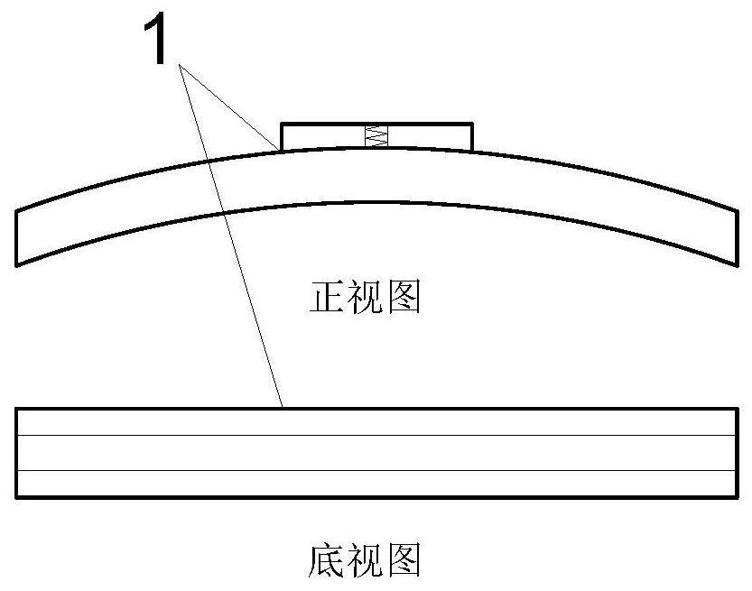
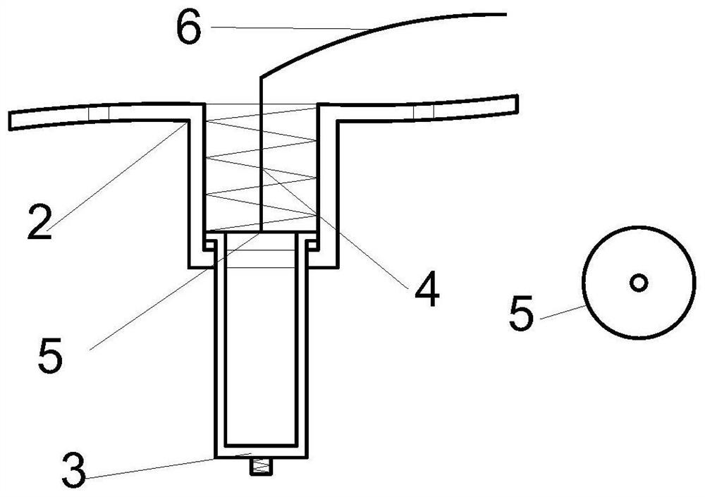
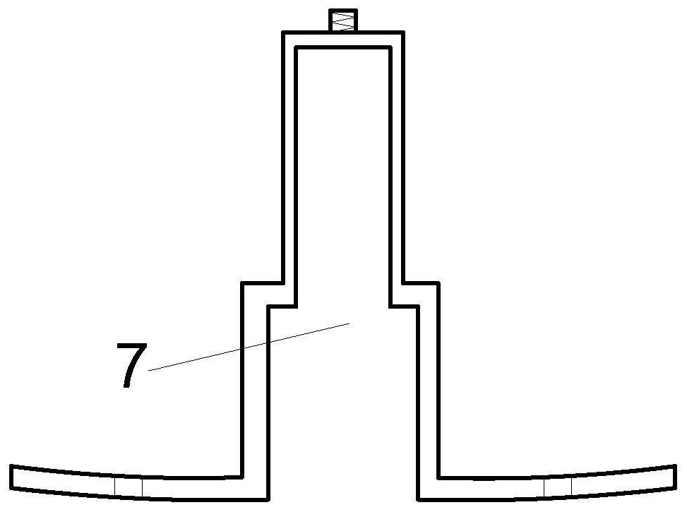
[0042] The upper pressing unit includes: a pressing head 1 , an upper sleeve 2 , a lower sleeve 3 , a sleeve spring 4 , and a pressing piece 5 . Two sets of one type are installed on both sides of the upper part of the round frame 8 respectively, and are riveted through the riveting holes 9 on both sides of the upper casing 2 and the riveting holes 9 on both sides of the upper part of the round frame 8 . The function of the pressing unit is to perform pressing operation on the tested object.

[0043] like figure 1 and figure 2 As shown, one side of the compression head 1 is a cuboid protrusion, and the center of the protrusion is processed with a threaded hole with an internal thread; the other side ...


PUM


Abstract

The invention discloses an adjustment frame capable of realizing surface rotation, which comprises an upper pressing unit, a lower rotating unit, a round frame, a lower rotating rod, an upper knob, a square frame, an upper cover, a constraint unit, a bottom foot unit and a lower pressing unit. unit, the two pressing heads and spring parts of the upper pressing unit and the lower pressing unit realize the clamping of the measured piece, wherein two sets of upper pressing units are installed on both sides of the upper part of the round frame, and the round frame is used Make the tested piece rotate on the front and rear surfaces of the tested piece, and realize positioning, clamping and vibration reduction. During the clamping and surface rotation of the tested piece by the adjusting frame of the present invention, the risk of the surface of the tested piece being easily defaced is avoided because the knob is used for rotation and related components are used to constrain, and the risk of being easily stained in many cases is avoided. The possibility of measurement error is included in the process of adjusting the tilt and clamping position for the first time, reducing the overall structural vibration and reducing vibration error.

Description

technical field [0001] The invention relates to an adjustment frame that can realize surface rotation, especially the adjustment frame that can realize the rotation of the front and rear surfaces of the measured object through the set adjustment frame accessory device, which can clamp and rotate the measured object, and is suitable for optical lenses clamping and adjustment. technical background [0002] Optical lenses play an important role in the design and construction of optical systems. Using laser interferometer to measure the surface of optical lens is a widely used method. [0003] When performing laser interferometry, the optical lens as the measured object needs to be clamped by the adjustment frame and placed in front of the interferometer, and because the interferometry technology is sensitive to factors such as vibration and noise, the adjustment frame needs to have vibration reduction At the same time, when measuring the measured part, it is often necessary t...

Claims


Application Information

Patent Timeline
Patent Type & Authority Patents(China)
IPC IPC(8): B25H1/06B25H1/08B25H1/10G01B11/24
CPCB25H1/06B25H1/08B25H1/10G01B11/2441
Inventor 常林何婷婷于瀛洁闫恪涛孙涛
Owner SHANGHAI UNIV
Why Eureka
Try Eureka