Supercharge Your Innovation With Domain-Expert AI Agents!

Centrifugal blower

A centrifugal and blower technology, which is applied in mechanical equipment, engine manufacturing, non-variable pumps, etc., can solve the problem of increased filter pressure loss, etc.

Active Publication Date: 2021-06-29
DENSO CORP
View PDF6 Cites 1 Cited by
  • Summary
  • Abstract
  • Description
  • Claims
  • Application Information

AI Technical Summary

Problems solved by technology

Therefore, if the air volume passing through each area of ​​the filter directly above the openings on the left and right on the outer side of the cylindrical part of the separation cylinder varies, the pressure loss of the filter as a whole may increase.

Method used


Image

  • Centrifugal blower
  • Centrifugal blower
  • Centrifugal blower

Examples


no. 1 approach

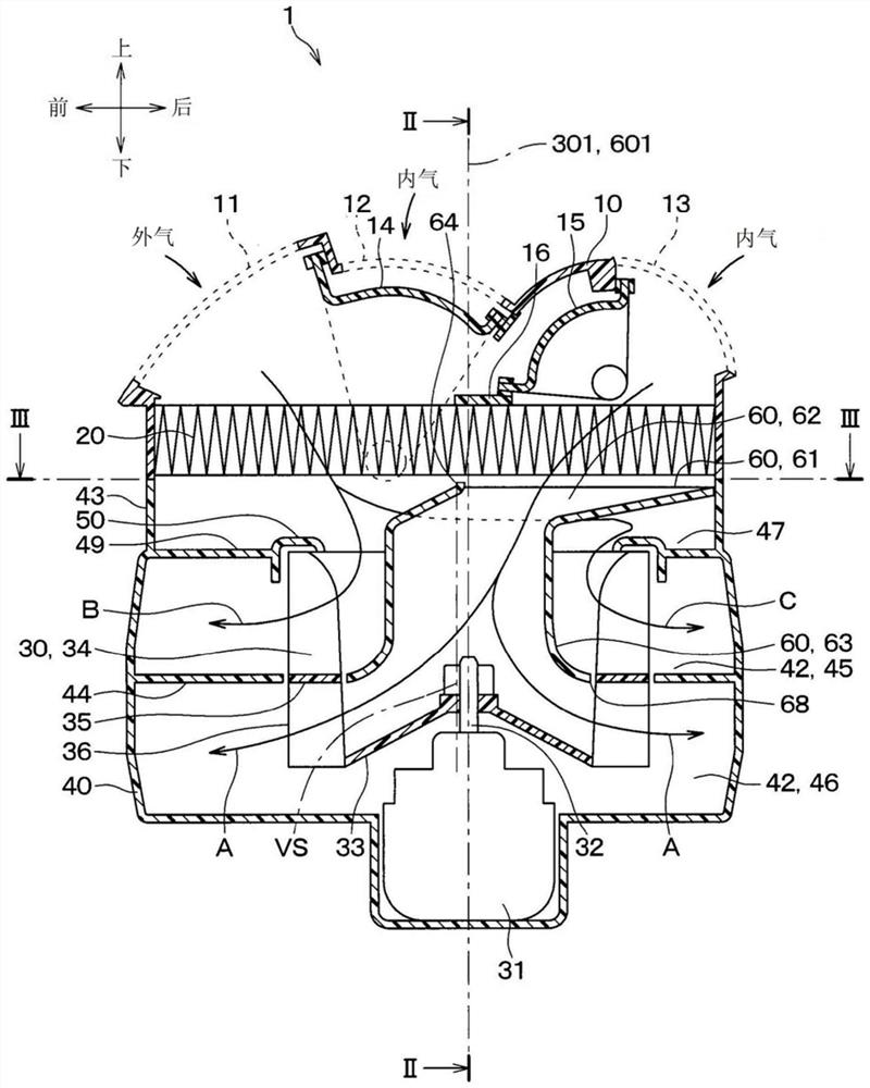
[0044] A first embodiment will be described with reference to the drawings. The centrifugal blower 1 of the present embodiment is suitable for a vehicle air conditioner of a double-flow type of internal and external air. This centrifugal blower 1 is a blower capable of distinguishing between vehicle interior air (hereinafter referred to as internal air) and vehicle outdoor air (hereinafter referred to as external air), sucking them in and blowing them out simultaneously.

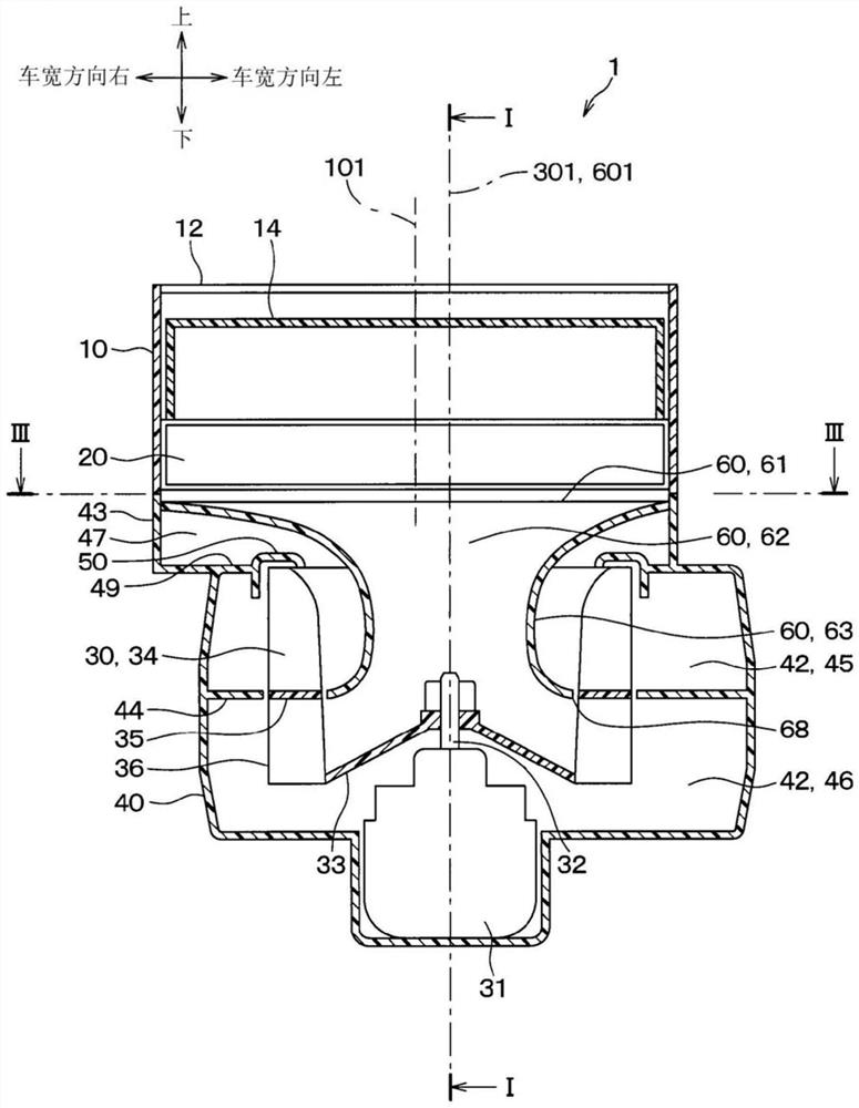
[0045] Such as Figure 1 ~ Figure 4 As shown, the centrifugal blower 1 includes an inner and outer air box 10 , a filter 20 , an impeller 30 , a scroll case 40 , a bell mouth 50 , a partition wall 44 , a separation cylinder 60 , and the like.

[0046]The inner and outer air boxes 10 are disposed on the upper part of the centrifugal blower 1 . The inner and outer air box 10 has an outside air inlet 11 , a first inside air inlet 12 , and a second inside air inlet 13 in order from the vehicle front side. The...

no. 2 approach

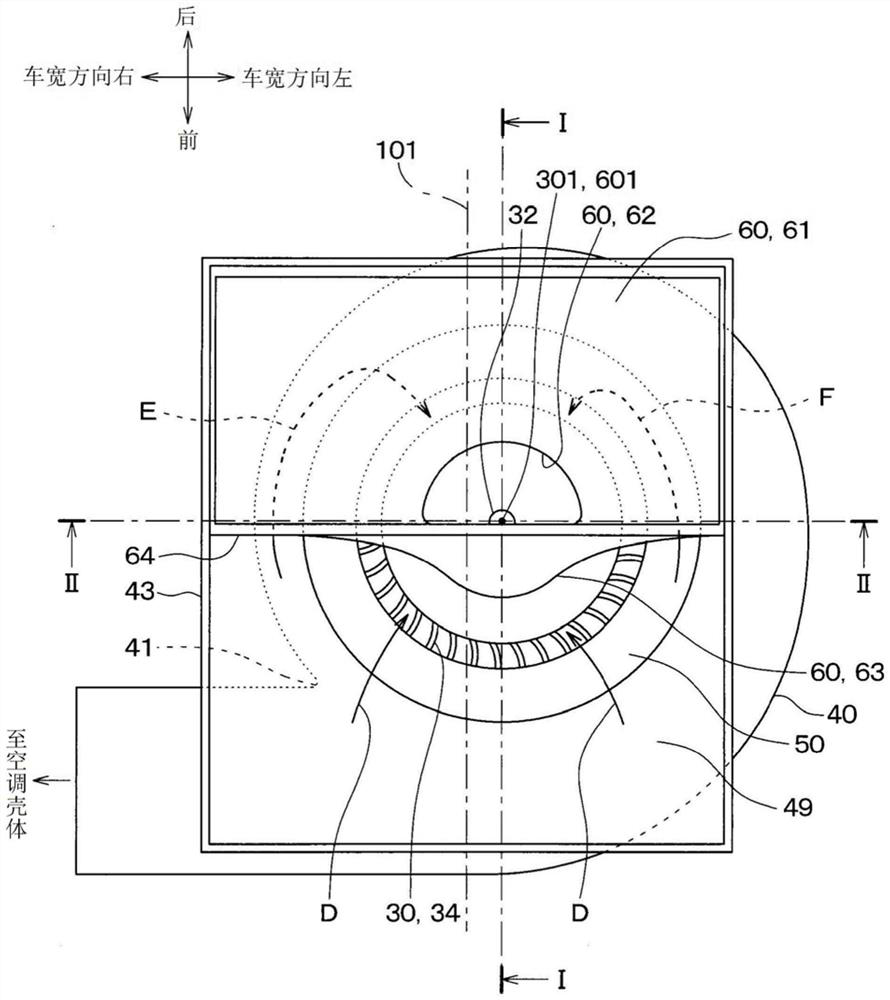
[0074] Such as Image 6 and Figure 7 As shown, in the second embodiment, the air introduction plate 61 of the separation cylinder 60 has: the first surface 65 located on the first opening 71 side, the second surface 66 located on the second opening 72 side, and the The stepped surface 67 connecting the first surface 65 and the second surface 66 . The second face 66 is disposed closer to the bell mouth 50 than the first face 65 is. In addition, in the second embodiment, the center 101 of the inner and outer air tank 10 is also located at a position deviated to the first opening 71 side with respect to the rotation shaft 301 of the impeller 30 and the central axis 601 of the cylindrical portion 63 included in the separation cylinder 60 . Location.

[0075] According to the above configuration, in the second embodiment, the cross-sectional area of ​​the flow path of the region of the first opening 71 on the side closer to the air introduction plate 61 than the impeller 30 is ...

no. 3 approach

[0077] Such as Figure 8 and Figure 9 As shown, in the third embodiment, the air introduction plate 61 included in the separation cylinder 60 is positioned relative to the bell mouth in such a manner that the portion on the second opening 72 side is closer to the bell mouth 50 than the portion on the first opening 71 side. 50 tilt. In addition, in the third embodiment, the center 101 of the inner and outer air tanks 10 is also located at a position deviated from the rotation shaft 301 of the impeller 30 and the central axis 601 of the cylindrical portion 63 of the separation cylinder 60 toward the first opening 71 side. Location.

[0078] According to the above configuration, in the third embodiment, the cross-sectional area of ​​the flow path of the region of the first opening 71 on the side closer to the air introduction plate 61 than the impeller 30 is larger than that of the second opening 72 compared to the impeller 30 . The cross-sectional area of ​​the flow path in ...


PUM


Abstract

Air flowing from a filter (20) to an air introduction plate (61) of a separation cylinder (60) passes inside a cylindrical part (63) of the separation cylinder (60) and flows to a lower air passage (46) via an impeller (30). Air flowing from the filter (20) to a region other than the air introduction plate (61) of the separation cylinder (60) passes outside the cylindrical part (63) of the separation cylinder (60) and flows to an upper air passage (45) via the impeller (30). In a flow passage in which air flows from the filter (20) to the upper air passage (45), a virtual plane (VS) is defined as being parallel to the rotation axis (301) of the impeller (30) and including an outer edge (64) of the air introduction plate (61). In a cross section of the flow passage on the virtual plane (VS), a cross section of the flow passage on the side closer to a nose part (41) across the separation cylinder (60) is referred to as a first opening (71), and a cross section of the flow passage on the farther side from the nose part (41) is referred to as a second opening (72). The cross-sectional area of the flow passage in the first opening (71) is larger than the cross-sectional area of the flow passage in the second opening (72).

Description

[0001] Cross-references to related applications [0002] This application is based on Japanese Patent Application No. 2018-216354 for which it applied on November 19, 2018, and the description content is incorporated here by reference. technical field [0003] The invention relates to a single-side suction centrifugal blower. Background technique [0004] Conventionally, there is known a one-side suction type centrifugal blower capable of distinguishing the air inside the vehicle and the air outside the vehicle and simultaneously sucking them in. [0005] In the centrifugal blower mechanism described in Patent Document 1, the air taken in from the air intake casing (hereinafter referred to as the inner and outer air box) is sucked into the inner side of the impeller through a filter, and blown out to the radially outer side of the impeller. ventilation path. The air passage on the outside in the radial direction of the impeller is partitioned by the partition wall into an ...

Claims


Application Information

Patent Timeline
IPC IPC(8): F04D29/44F04D29/28F04D29/70
CPCF04D17/16F04D25/08F04D29/282F04D29/4213F04D29/441F05D2250/51F04D29/703B60H1/00471B60H2001/00085F04D17/10F04D29/4226F04D29/424F04D17/162
Inventor 小坂翔小田修三
Owner DENSO CORP
Features
  • R&D
  • Intellectual Property
  • Life Sciences
  • Materials
  • Tech Scout
  • Unparalleled Data Quality
  • Higher Quality Content
  • 60% Fewer Hallucinations
Learn More