
Connecting rod structure, robot finger and robot

A connecting rod structure and connecting rod technology, applied in the field of robot fingers and robots, connecting rod structure, can solve the problem that the connecting rod mechanism cannot move passively

Active Publication Date: 2021-07-02
UBTECH ROBOTICS CORP LTD
View PDF6 Cites 1 Cited by
  • Summary
  • Abstract
  • Description
  • Claims
  • Application Information

AI Technical Summary

Problems solved by technology

[0003] The purpose of the embodiment of the present application is to provide a connecting rod structure, a robot finger and a robot to solve the problem that the existing connecting rod mechanism cannot move passively when it is subjected to external force technical problem

Method used


Image

  • Connecting rod structure, robot finger and robot
  • Connecting rod structure, robot finger and robot
  • Connecting rod structure, robot finger and robot

Examples


Embodiment Construction

[0039] In order to make the technical problems, technical solutions and beneficial effects to be solved by the present application clearer, the present application will be further described in detail below in conjunction with the accompanying drawings and embodiments. It should be understood that the specific embodiments described here are only used to explain the present application, and are not intended to limit the present application.

[0040] In the description of the embodiments of the present application, it should be understood that the terms "length", "width", "upper", "lower", "front", "rear", "left", "right", "vertical ", "horizontal", "top", "bottom", "inner", "outer" and other indicated orientations or positional relationships are based on the orientations or positional relationships shown in the drawings, and are only for the convenience of describing the embodiments of the present application and Simplified descriptions do not indicate or imply that the device o...


PUM


Abstract

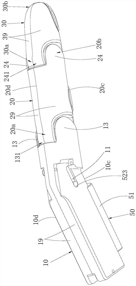
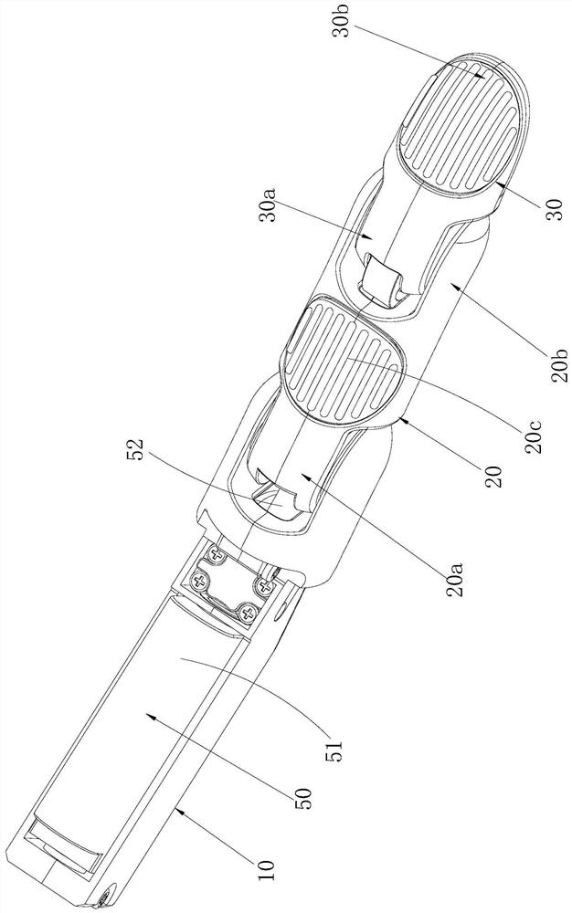
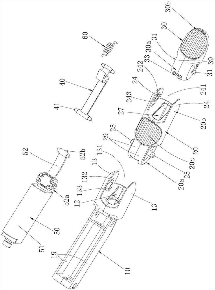
The invention belongs to the technical field of robot accessories, and particularly relates to a connecting rod structure, a robot finger and a robot. In the connecting rod structure, a fixing frame, a first rod piece, a second rod piece and a connecting rod form a four-rod mechanism, and in combination with a driving assembly and an elastic piece, the active bending, straightening and passive bending motion of the four-rod mechanism can be achieved. No matter whether a linear driving piece works or not, when the second rod piece is subjected to external force, the second rod piece can swing, the elastic piece is compressed to store energy, the first rod piece is in linkage with the connecting rod, the first rod piece swings in the swinging direction of the second rod piece, and the passive bending motion is achieved. During the passive bending motion, interference between the first rod piece and a transmission rod cannot occur, and the situation that the four-rod mechanism is damaged due to the external force is reduced. After the external force is removed, the elastic piece releases energy to drive the second rod piece to reset, the first rod piece is in linkage with the connecting rod, and the straightening motion is achieved. The connecting rod structure can be applied to occasions needing two-way active motion and one-way passive motion, such as the robot finger.

Description

technical field [0001] The application belongs to the technical field of robot accessories, and in particular relates to a connecting rod structure, a robot finger and a robot. Background technique [0002] At present, the most commonly used transmission method for robot fingers is connecting rod transmission, which is generally a four-bar mechanism with a single degree of freedom, that is, a driving member controls the movement of the connecting rod mechanism in a fixed path to realize the bending and straightening of the robot finger. . As a moving part, the traditional four-bar mechanism is easily damaged by the external force of collision and impact. When the four-bar mechanism is subjected to external force, it cannot passively bend and move, and the movement appears stiff and not compliant. Contents of the invention [0003] The purpose of the embodiments of the present application is to provide a link structure, a robot finger and a robot, so as to solve the techni...

Claims


Application Information

Patent Timeline
IPC IPC(8): B25J15/00B25J15/08B25J18/00
CPCB25J18/00B25J15/0009B25J15/08B25J15/022B25J15/12
Inventor 黄忠葵陈明罗琪翔丁宏钰谢铮范文华
Owner UBTECH ROBOTICS CORP LTD
Learn More