Geology information anisotropy distribution rule analysis method and device and electronic equipment

A technology of anisotropy and distribution law, applied in the field of geospatial data distribution pattern analysis, it can solve the problem of ignoring the local characteristics of geospatial data, and achieve the effect of good indication.

Active Publication Date: 2021-07-02
INST OF GEOMECHANICS
View PDF4 Cites 0 Cited by
  • Summary
  • Abstract
  • Description
  • Claims
  • Application Information

AI Technical Summary

Problems solved by technology

[0006] The singularity index calculated by using an isotropic square window reflects the local isotropic and homogeneous geochemical distribution, while the actual spatial distribution of geochemical concentrations is affected by multi-phase and multi-directional geological activities and has anisotropy and Heterogeneity, that is, different distribution patterns in different directions, so the traditionally used singularity index calculation method based on an isotropic square window ignores the anisotropic local characteristics of geospatial data to a certain extent
[0007] However, the method of determining the singularity index by constructing a series of rectangular windows in different directions to calculate the maximum change trend in each direction takes into account the anisotropy of the change, but the described singularity still has directional characteristics, which is suitable for the directional distribution considered. This method ignores to some extent the different distribution patterns of geospatial data caused by different geological processes

Method used


Image

  • Geology information anisotropy distribution rule analysis method and device and electronic equipment
  • Geology information anisotropy distribution rule analysis method and device and electronic equipment
  • Geology information anisotropy distribution rule analysis method and device and electronic equipment

Examples


Embodiment Construction

[0057] The technical solutions in the embodiments of the present application will be described below with reference to the drawings in the embodiments of the present application.

[0058] Like numbers and letters denote similar items in the following figures, so that once an item is defined in one figure, it does not require further definition and explanation in subsequent figures. Meanwhile, in the description of the present application, the terms "first", "second" and the like are only used to distinguish descriptions, and cannot be understood as indicating or implying relative importance.

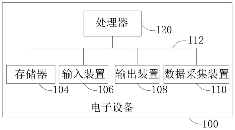
[0059] Please refer to figure 2 , which is a schematic structural diagram of the electronic device 100 provided in the embodiment of the present application. The electronic device 100 includes: one or more processors 120 , and one or more memories 104 storing instructions executable by the processors 120 . Wherein, the processor 120 is configured to execute the method for analyzing th...


PUM


Abstract

The invention provides a geology information anisotropy distribution rule analysis method and device and electronic equipment. The method comprises the steps: acquiring sampling values of space sampling points in a research area; taking any sampling point as a center, and constructing a plurality of elliptical windows with different equivalent radiuses and compression coefficients under each azimuth angle by changing the azimuth angle; for a plurality of elliptical windows under the same azimuth angle, selecting an optimal ellipse under the azimuth angle according to a relative difference value between a sample mean value of all sampling points in the elliptical windows and a preset classification threshold value; and according to the optimal ellipse under the various azimuth angles, the equivalent radius of the optimal ellipse and the sample mean value of all the sampling points in the optimal ellipse, calculating the singularity index of the sampling point in the center, and obtaining the anisotropy distribution rule of the spatial sampling points in the research area. The method can objectively, systematically and quantitatively reflect different distribution modes of geoscience information in different directions of the space, and has good indication significance.

Description

technical field [0001] The present application relates to the field of geospatial data distribution pattern analysis, in particular, to a method and device, electronic equipment, and a computer-readable storage medium for analyzing the anisotropy distribution law of geoscience information. Background technique [0002] The singularity index (singularity) is used for spatial quantification through fractal and multifractal methods, and measures the huge accumulation of matter or the release of energy generated by matter in a relatively narrow time or space interval. [0003] The classical calculation method of the singularity index is obtained by the square window method, such as figure 1 shown. The estimation process is as follows: Take the geochemical sediment sampling point data as an example; the first step is to select any sampling point and define a series of square windows with this point as the geometric center: ε 1 ×ε 1 , ε 2 ×ε 2 ,...,ε i ×ε i . The second st...

Claims


Application Information

Patent Timeline
IPC IPC(8): G06F17/10G06K9/62
CPCG06F17/10G06F18/241
Inventor 王文磊赵洁祝茂强王文君
Owner INST OF GEOMECHANICS
Why Eureka
Try Eureka