Aerobics flexibility training auxiliary device
An auxiliary device, aerobics technology, applied in the field of training equipment, can solve problems such as leg ligament injuries
- Summary
- Abstract
- Description
- Claims
- Application Information
AI Technical Summary
Problems solved by technology
Method used
Image
Examples
Embodiment 1
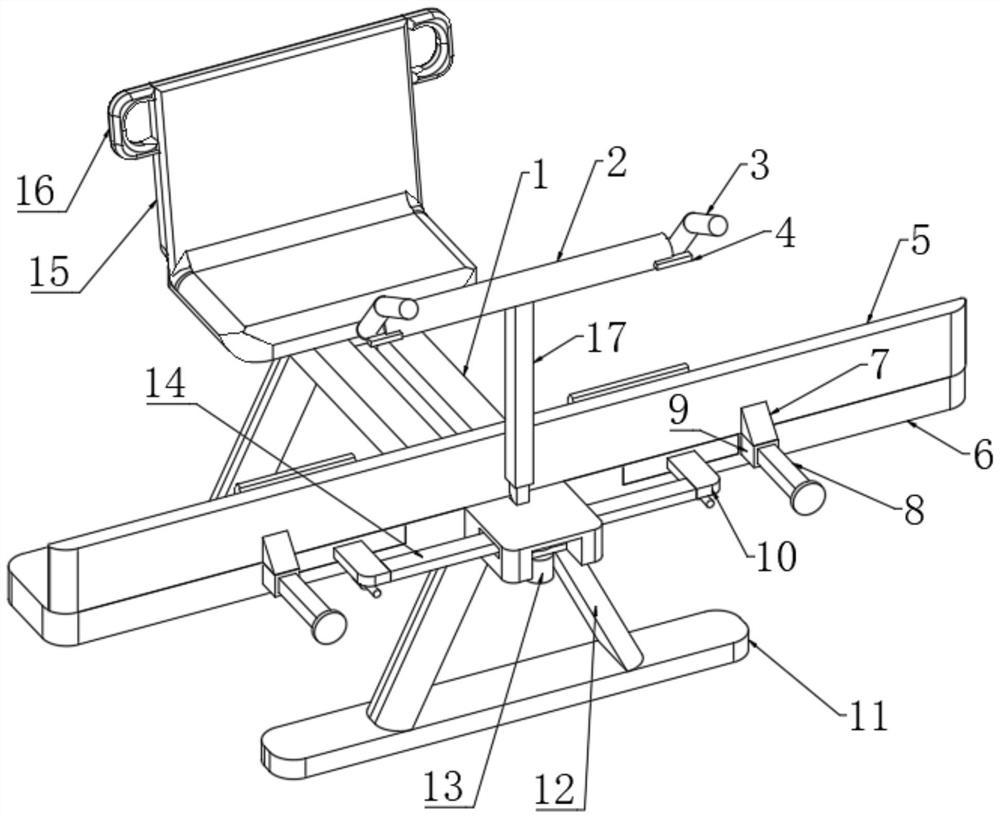
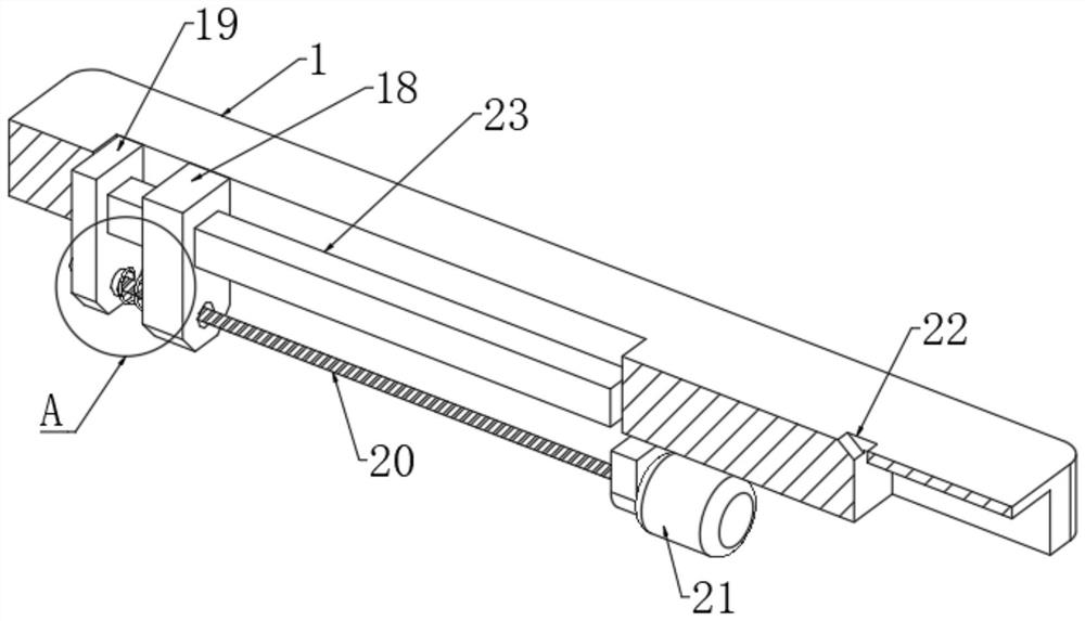
[0028] refer to Figure 1 to Figure 7, an aerobics flexibility training auxiliary device, comprising a mounting plate 1, two supporting plates 11 are arranged below the mounting plate 1, and the upper ends of the two supporting plates 11 are obliquely fixedly connected with two supporting legs 12, and the two supporting legs 12 are distributed in a figure-eight shape, the upper end of the supporting leg 12 is fixedly connected with the lower end of the mounting plate 1, the side wall of the mounting plate 1 is provided with a strip-shaped through hole, and a rectangular rod 23 is fixedly connected in the strip-shaped through hole, and the rectangular rod 23 The rod wall is connected with a transmission mechanism. The transmission mechanism includes a transmission block 19 and a connecting block 18. The side walls of the transmission block 19 and the connecting block 18 are all slidably socketed with the rod wall of the rectangular rod 23 through a square hole. The upper end of ...
Embodiment 2
[0030] Embodiment 2: the difference based on Embodiment 1 is;
[0031] refer to figure 1 and Figure 5 , the reciprocating mechanism includes a strip-shaped opening 26 provided on the wall of the transmission rod 14, a transmission shaft 27 is slidably connected in the strip-shaped opening 26, a turntable 28 is fixedly connected to the lower end of the transmission shaft 27, and a fixed plate is fixedly connected to the gap. One side of the plate is fixedly connected with a second motor 13, the output end of the second motor 13 runs through the side wall of the fixed plate and is fixedly connected with the lower end of the turntable 28 coaxially, and both ends of the transmission rod 14 are fixedly connected with a pull rod 10, The two pull rods 10 are parallel to each other, one end of the pull rod 10 is fixedly connected to one side of the rectangular plate 31, the lower end of the pull rod 10 is fixedly connected with a directional sliding sleeve 29, and the directional sl...
Embodiment 3
[0033] Embodiment 3: the difference based on embodiment 1 is;
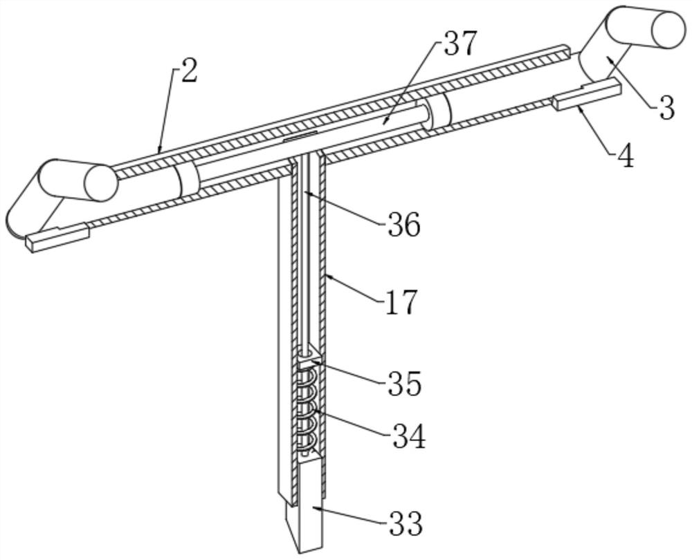
[0034] refer to figure 1 and image 3 , the fixing mechanism includes a horizontal tube 2, the tube wall of the horizontal tube 2 is fixedly connected with the upper end of the rectangular tube 17 through an assembly hole, a positioning block 33 is slidingly sleeved in the rectangular tube 17, and one end of the positioning block 33 extends into the fixing groove 22 and An inclined surface is provided, and the other end of the positioning block 33 is fixedly connected with a stay cord 36, one end of the stay cord 36 extends into the horizontal tube 2, the side wall of the stay cord 36 is sleeved with a second spring 34, and one end of the second spring 34 It is fixedly connected with the upper end of the positioning block 33, and the other end of the second spring 34 is fixedly connected with the positioning piece 35, the side wall of the positioning piece 35 is socketed with the pull rope 36 through the round mo...
PUM
 Abstract
Description
Claims
Application Information
 - R&D
- Intellectual Property
- Life Sciences
- Materials
- Tech Scout
- Unparalleled Data Quality
- Higher Quality Content
- 60% Fewer Hallucinations
Browse by: Latest US Patents, China's latest patents, Technical Efficacy Thesaurus, Application Domain, Technology Topic, Popular Technical Reports.
© 2025 PatSnap. All rights reserved.Legal|Privacy policy|Modern Slavery Act Transparency Statement|Sitemap|About US| Contact US: help@patsnap.com


