Plate punching equipment for intelligent manufacturing
A technology of intelligent manufacturing and equipment, applied in the direction of wood punching, etc., can solve the problems of poor punching quality, unstable punching position, poor working environment, etc.
- Summary
- Abstract
- Description
- Claims
- Application Information
AI Technical Summary
Problems solved by technology
Method used
Image

Examples
Embodiment 1
[0079] A plate punching equipment for intelligent manufacturing, such as figure 1 As shown, it includes a base 1, a support frame 2, a driving transport mechanism 3 and a stamping and punching mechanism 4. There are multiple support frames 2 on the top of the base 1, a drive transport mechanism 3 is provided in the middle of the top of the base 1, and the left side of the top of the base 1 A stamping and punching mechanism 4 is provided.
[0080] The staff places the plate in the driving transport mechanism 3, then starts the driving transport mechanism 3 and the stamping and punching mechanism 4 to work, the driving transport mechanism 3 drives the plate to move into the stamping and punching mechanism 4, and the punching parts of the stamping and punching mechanism 4 Move down to punch the plate. After the punching is completed, the stamping parts of the punching and punching mechanism 4 are reset. At this time, the staff takes out the punched plate, drives the transport mec...
Embodiment 2
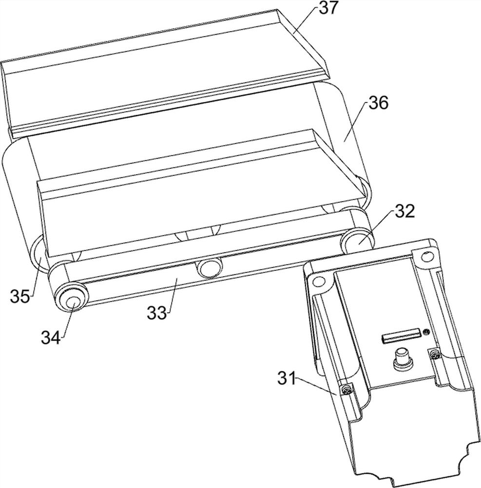
[0082] On the basis of Example 1, such as Figure 2-3 As shown, the driving transport mechanism 3 includes a servo motor 31, a drive shaft 32, a first transmission belt 33, a first transmission shaft 34, a sleeve shaft 35, a conveyor belt 36 and a limit plate 37, and the front side of the top of the base 1 is provided with a servo motor. 31, the output end of the servo motor 31 is provided with a drive shaft 32, the drive shaft 32 is rotatably connected to the support frame 2 in the middle, and the support frame 2 in the middle is rotatably provided with two first transmission shafts 34, and the first transmission shaft 34 is connected to the A first transmission belt 33 is provided between the front sides of the drive shaft 32, a sleeve shaft 35 is provided on the first transmission shaft 34 and the drive shaft 32, a conveyor belt 36 is provided between the sleeve shafts 35 on the left and right sides, and a support frame in the middle 2 The top is provided with two limiting ...
Embodiment 3
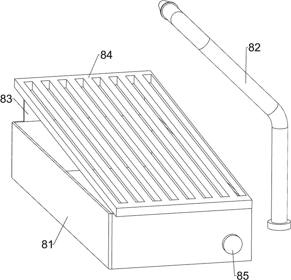
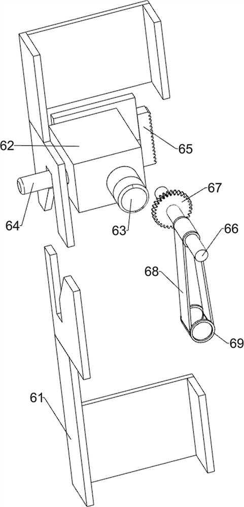
[0086] On the basis of Example 2, such as Figure 3-8 As shown, a clamping limit mechanism 5 is also included, and the clamping limit mechanism 5 includes a first limit slide rail 51, a first support plate 52, a first spring 53, a stabilizing column 54, a second slide rail 55, The second spring 56, the sliding plate 57, the lower pressing block 58 and the vertical plate 59, the base 1 top middle part is provided with the first limit slide rail 51 symmetrically, and the vertical plate 59 is slidable between the first limit slide rails 51 , the outside of the support frame 2 in the middle is symmetrically provided with a first support plate 52, the first spring 53 is arranged between both sides of the vertical plate 59 and the first support plate 52 on the same side, and the lower left side of the vertical plate 59 is symmetrically provided with Stabilizing column 54, vertical plate 59 left middle part is provided with second slide rail 55, is provided with slide plate 57 slidin...
PUM
 Abstract
Description
Claims
Application Information
 - R&D
- Intellectual Property
- Life Sciences
- Materials
- Tech Scout
- Unparalleled Data Quality
- Higher Quality Content
- 60% Fewer Hallucinations
Browse by: Latest US Patents, China's latest patents, Technical Efficacy Thesaurus, Application Domain, Technology Topic, Popular Technical Reports.
© 2025 PatSnap. All rights reserved.Legal|Privacy policy|Modern Slavery Act Transparency Statement|Sitemap|About US| Contact US: help@patsnap.com