Supercharge Your Innovation With Domain-Expert AI Agents!

Plastic pipe injection molding cooling device

A cooling device and plastic tube technology, which is applied to tubular items, other household appliances, household appliances, etc., can solve the problems of shrinking and slowing down the inner diameter of the plastic tube injection cooling box.

Inactive Publication Date: 2021-07-06
广州诺旗科技有限公司
View PDF4 Cites 0 Cited by
  • Summary
  • Abstract
  • Description
  • Claims
  • Application Information

AI Technical Summary

Problems solved by technology

[0002] The plastic pipe injection molding cooling box is mainly used for cooling and forming plastic pipes. The molten plastic is injected into the plastic pipe injection cooling box, and then the molten plastic is shaped into a tube through the plastic pipe injection cooling box, and finally the cooling fan is continuously The heat in the molten plastic is taken out, so that the plastic pipe can be molded and extruded inside the plastic pipe injection cooling box. Based on the above description, the inventors found that an existing plastic pipe injection cooling device mainly has the following Insufficient, for example: due to the high viscosity of polyvinyl chloride plastic after melting, so that if the extrusion speed of the plastic pipe injection cooling box is slowed down, it is easy to make part of the molten polyvinyl chloride plastic adhere to the plastic If the inner wall of the pipe injection cooling box is not cleaned in time, the inner diameter of the plastic pipe injection cooling box will easily shrink

Method used


Image

  • Plastic pipe injection molding cooling device
  • Plastic pipe injection molding cooling device
  • Plastic pipe injection molding cooling device

Examples


Embodiment 1

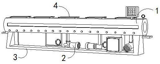
[0027] For example figure 1 -example Figure 5 Shown:

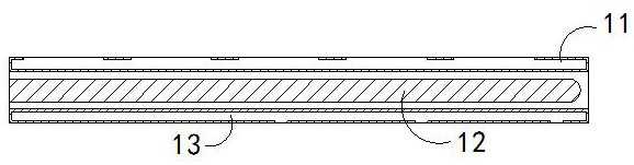
[0028] The invention provides a cooling device for injection molding of plastic pipes, the structure of which includes a cooling box 1, a heat dissipation fan 2, a base 3, and a ventilation chamber 4. The heat dissipation fan 2 is fixed at the bottom of the cooling box 1, and the bottom of the ventilation chamber 4 Embedded in the upper position of the cooling box 1, the bottom position of the cooling box 1 is welded to the top of the base 3; the cooling box 1 includes an upper cavity 11, a molding rod 12, and a lower cavity 13. The placement chamber 11 and the lower placement chamber 13 are an integral structure, and the molding rod 12 runs through between the upper placement chamber 11 and the lower placement chamber 13 .

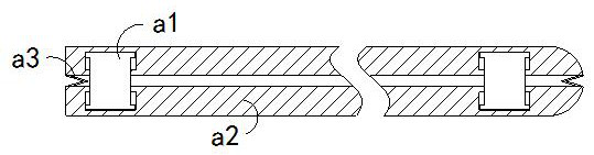
[0029] Wherein, the molding rod 12 includes a linkage block a1, an outer expansion plate a2, and a booster piece a3. Between the inner sides of the expansion board a2, there are two outer expansio...

Embodiment 2

[0035] For example Figure 6 -example Figure 9 Shown:

[0036]Wherein, the upper swing plate b4 includes a force plate b41, an impact block b42, and a bottoming block b43, the force plate b41 is embedded in the inner position of the bottom block b43, and the impact block b42 is installed on the force plate b41 The internal position of the impact block b42 is made of high-density alloy steel. Through the swinging force generated by the mechanism, the impact block b42 can repeatedly impact the upper end of the inner wall of the force plate b41, so that the adhesion on the bottoming can be eliminated. The polyvinyl chloride plastic on the upper surface of block b43 vibrates until it becomes loose.

[0037] Wherein, the stressed plate b41 includes an upper extension rod c1, a lower frame c2, and a board surface c3. The bottom of the upper extension rod c1 is provided with five, and evenly distributed in parallel inside the board surface c3, the vibration received by the mechan...


PUM


Abstract

The invention discloses a plastic pipe injection molding cooling device. The plastic pipe injection molding cooling device structurally comprises a cooling box, a cooling fan, a base and a ventilation cavity, the cooling fan is fixed to the bottom of the cooling box, the bottom of the ventilation cavity is embedded and fixed to the upper end of the cooling box, and the bottom of the cooling box is welded to the top of the base. An elescopic block which is not extruded by the inner side of an external expansion plate can be pulled through an elastic strip to shrink inwards along a plate block, so that the top of the telescopic block can collide with the inner wall of an upper cavity and the inner wall of a lower cavity, the telescopic block can crush solidified polyvinyl chloride plastics attached to the inner wall of the upper cavity and the inner wall of the lower cavity, an upward extending rod can upwards slide and extend out along the plate face through vibration borne by a stress plate, then a contact plate can be pushed to be attached to the inner wall of the plate face all the time through a boosting strip, and therefore the situation that molten polyvinyl chloride plastic which is not completely solidified enters the space between the upward extending rod and the plate face can be avoided.

Description

technical field [0001] The invention relates to the field of equipment for injection molding cooling, in particular to an injection molding cooling device for plastic pipes. Background technique [0002] The plastic pipe injection molding cooling box is mainly used for cooling and forming plastic pipes. The molten plastic is injected into the plastic pipe injection cooling box, and then the molten plastic is shaped into a tube through the plastic pipe injection cooling box, and finally the cooling fan is continuously The heat in the molten plastic is taken out, so that the plastic pipe can be molded and extruded inside the plastic pipe injection cooling box. Based on the above description, the inventors found that an existing plastic pipe injection cooling device mainly has the following Insufficient, for example: due to the high viscosity of polyvinyl chloride plastic after melting, so that if the extrusion speed of the plastic pipe injection cooling box is slowed down, it ...

Claims


Application Information

Patent Timeline
IPC IPC(8): B29C45/73B29C45/17B29L23/00
CPCB29C45/7337B29C45/1753B29L2023/00
Inventor 马映生
Owner 广州诺旗科技有限公司
Features
  • R&D
  • Intellectual Property
  • Life Sciences
  • Materials
  • Tech Scout
  • Unparalleled Data Quality
  • Higher Quality Content
  • 60% Fewer Hallucinations
Learn More