
Spectroscopic prism fixing component and projection light machine

A technology of beam splitting prism and fixed components, applied in optics, instruments, projection devices, etc., can solve the problem of no compact beam splitting prism, and achieve the effect of compact structure, small occupied space and high practicability

Active Publication Date: 2022-04-22
SHENZHEN ANHUA OPTOELECTRONICS TECH
View PDF6 Cites 0 Cited by
  • Summary
  • Abstract
  • Description
  • Claims
  • Application Information

AI Technical Summary

Problems solved by technology

However, for the spatial position of the beam-splitting prism to be changed to a structure in which the initial incident surface of the beam-splitting prism faces downward, there is currently no more mature solution that is compact in structure and can ensure the stability of the beam-splitting prism

Method used


Image

  • Spectroscopic prism fixing component and projection light machine
  • Spectroscopic prism fixing component and projection light machine
  • Spectroscopic prism fixing component and projection light machine

Examples


Embodiment Construction

[0053] In order to better illustrate the technical solution and beneficial effect of the beam splitting prism fixing assembly of the present invention, the projection light machine of a preferred embodiment of the invention will be introduced together with the introduction of the beam splitting prism fixing assembly of the present invention.

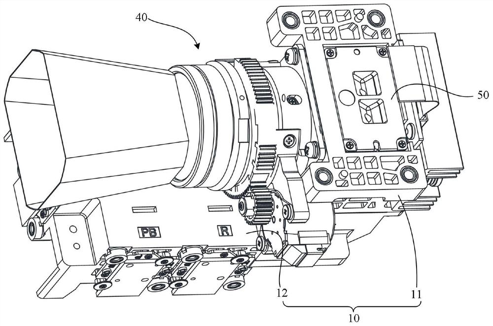
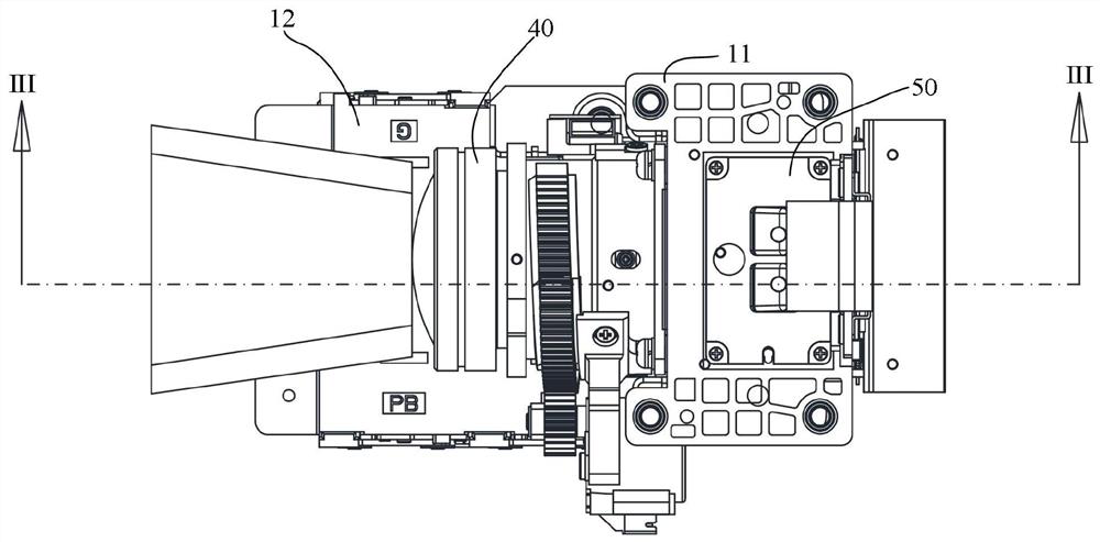
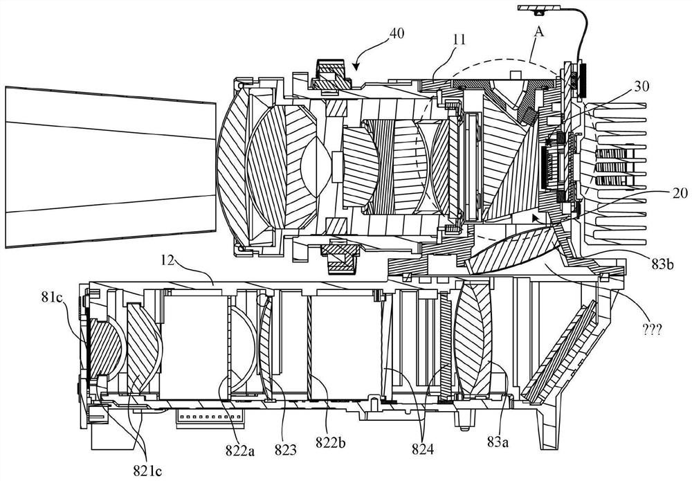
[0054] Please refer to Figure 1-6 , Figure 11 to Figure 14 as well as Figure 18 , in one embodiment, the light projection machine of the present invention includes a DMD light modulator 30, a projection lens 40 and a beam splitting prism fixing assembly, the DMD light modulator 30 is installed in the rear installation port 111b of the housing 10, and the projection lens 40 is installed in The front mounting opening 111a of the housing 10.

[0055] The dichroic prism fixing assembly includes a housing 10, a dichroic prism 20, an upper cover 50, a first elastic member 61, a second elastic member 62 and two third elastic members 63. Th...


PUM


Abstract

The invention discloses a light-splitting prism fixing assembly, which includes a casing, a light-splitting prism, an upper cover, a first elastic piece, a second elastic piece and two third elastic pieces. side wall; the inner cavity of the housing is provided with a rear limiting surface, the first side wall and the second side wall are respectively provided with a first boss and a second boss, and each of the first boss and the second boss is provided with a The inclined first convex line, the side limiting surface is formed on the first convex platform, and the lower limiting surface is formed on the first convex line; the beam splitting prism is installed in the inner cavity of the housing, and the upper cover is fixed to cover the installation port; the first The elastic piece connects one end face of the beam splitting prism and the second boss; the second elastic piece connects the upper end of the beam splitting prism and the upper cover; two third elastic pieces are respectively located on the front side of the first boss and the second boss, and the two second The three elastic parts are all connected to the lower end of the beam splitting prism and the housing. The invention also discloses a projection light machine, and the structure of the stable dichroic prism in the invention is highly practical and compact.

Description

technical field [0001] The invention relates to the technical field of optical projection equipment, in particular to a beam splitting prism fixing assembly and a projection light machine. Background technique [0002] The core component of the micro projector is the projection light engine, and the beam splitting prism and the DMD light modulator are the two core components of the projection light engine. The accuracy of the relative position between the dichroic prism and the DMD light modulator has a very important influence on the projection quality. In the production process, in order to modulate the projection light machine, the common methods include: 1. Use the DMD light modulator as a fixed reference to adjust the position of the beam splitting prism; 2. Contrary to the first method, use the beam splitting prism as a fixed reference Adjust the position of the DMD light modulator and / or lens. The latter approach requires the assembly of the beam splitting prism its...

Claims


Application Information

Patent Timeline
Patent Type & Authority Patents(China)
IPC IPC(8): G03B21/00G03B21/14
CPCG03B21/008G03B21/142G03B21/145
Inventor 朱青孙峰杨浩高怡玮
Owner SHENZHEN ANHUA OPTOELECTRONICS TECH
Learn More