Floating connector and conductive structure

A technology of floating connectors and conductive structures, applied in the direction of connection, circuit, coupling device, etc., which can solve the problems of unchangeable assembly sequence, cumbersome assembly steps, and complicated connection structure

Pending Publication Date: 2021-07-06
CHINA AVIATION OPTICAL-ELECTRICAL TECH CO LTD
View PDF7 Cites 0 Cited by
  • Summary
  • Abstract
  • Description
  • Claims
  • Application Information

AI Technical Summary

Problems solved by technology

[0003] Due to the limited space in the equipment box, the existing installation sequence is to fix the printed board first, then connect the printed board connector to the printed board, and finally insert the external connector into the equipment box to connect with the printed circuit board. Board-made connectors are plugged and mated, because the external connector is directly plugged with the printed board connector during installation, and the assembly sequence cannot be changed. If the external connector is inserted into the equipment box first, then the printed board connector Unable to move in the mating direction and thus unable to mate with external connectors
[0004] The problems existing in this assembly structure are: 1) The external connector is locked with the equipment box through bolts, that is, the external connector and the equipment box have a unique matching position. Or affected by vibration, when there is an offset with the equipment box, if in order to ensure that the external connector and the printed board connector are mated, the connection position between the external connector and the equipment box will be misplaced, and the external connector cannot be locked in place. On the equipment box; if in order to ensure that the external connector can be locked on the equipment box, the mating position of the external connector and the printed board connector is misaligned, and the external connector cannot be mated with the printed board connector. The connector and the printed board connector have poor tolerance when mating; 2) The printed board is first fixed in the equipment box, the printed board connector is connected to the printed board, and the external connector is connected to the printed board. Board connector connection, complex connection structure, cumbersome assembly steps, and inconvenient operation

Method used


Image

  • Floating connector and conductive structure
  • Floating connector and conductive structure
  • Floating connector and conductive structure

Examples


Embodiment Construction

[0055] In order to further explain the technical means and effects of the present invention to achieve the intended purpose of the invention, the specific implementation, structure, characteristics and effects of the floating connector proposed according to the present invention will be described below in conjunction with the accompanying drawings and preferred embodiments. Details are as follows.

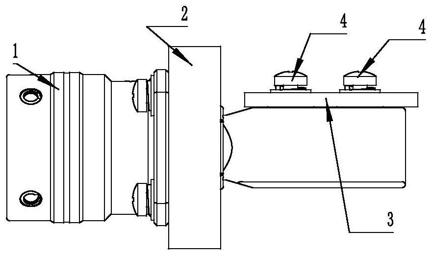
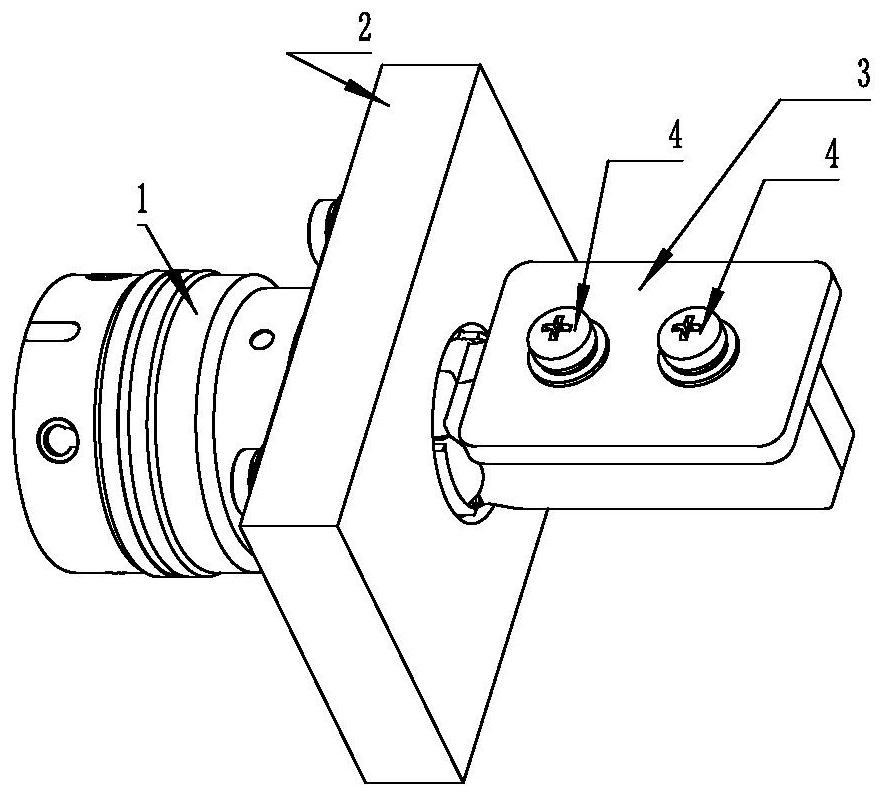
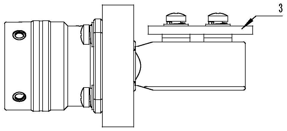
[0056] see Figure 1-15 , which is a structural diagram of each part of the floating connector of the present invention. The floating connector 1 includes a housing 5 for supporting the entire connector, and a flange 6 is provided on the housing 5 . The connector is fixed on the box wall 2 of the equipment box by screws passing through its flange 6, and the tail of at least one conductive structure 8 in the connector enters the equipment box through a hole in the box wall and is connected with the printed circuit board. The board 3 is contacted and conducted, and the external elec...


PUM


Abstract

The invention relates to a floating connector and a conductive structure. The floating connector comprises a shell, at least one conductive structure and an insulator, wherein the shell can be fixedly connected with a wall body of an equipment box body; the conductive structure is used for signal transmission; and the tail part of the conductive structure passes through an opening in the wall body of the equipment box body, enters the box body and is in contact conduction with the printed board through a connecting end which can float in the insulator along the direction towards or away from the printed board. The connector is matched with printed boards at different positions through floating of the tail of the conductive structure.

Description

technical field [0001] The invention belongs to the technical field of connectors, in particular to a floating connector. Background technique [0002] Some equipment is fixed with printed boards. In order to connect the printed boards in the equipment box with the circuit outside the equipment box, an external socket is generally installed on the box wall of the equipment box, and then the printed board is connected through the transfer. The connector connects the external socket with the printed board to realize power or signal transmission. [0003] Due to the limited space in the equipment box, the existing installation sequence is to fix the printed board first, then connect the printed board connector to the printed board, and finally insert the external connector into the equipment box to connect with the printed circuit board. The board connector is plugged and mated, because the external connector is directly plugged with the printed board connector during the inst...

Claims


Application Information

Patent Timeline
IPC IPC(8): H01R12/91
CPCH01R12/91
Inventor 刘向阳闫丰献许蔚王恒习冰寒张志中李立新韩云钊全硒硼柳先波田旭胡竣浩
Owner CHINA AVIATION OPTICAL-ELECTRICAL TECH CO LTD
Why Eureka
Try Eureka