A tension holding structure, tension holding device and vibrating wire equipment

A tension and protective sleeve technology, applied in the field of tension retention device, tension retention structure, and vibrating wire equipment, can solve the problems of small actual tension and reduced tension of the string, so as to improve stability, maintain stable tension, The effect of improving stability

Active Publication Date: 2022-05-27
厦门邦创信息技术有限公司
View PDF0 Cites 0 Cited by
  • Summary
  • Abstract
  • Description
  • Claims
  • Application Information

AI Technical Summary

Problems solved by technology

However, during the installation process of the existing tension-holding device for the tension in the cavity, after the installation is completed, the tension of the tension often becomes smaller, resulting in the actual tension of the tension being less than the set value

Method used


Image

  • A tension holding structure, tension holding device and vibrating wire equipment
  • A tension holding structure, tension holding device and vibrating wire equipment
  • A tension holding structure, tension holding device and vibrating wire equipment

Examples


Embodiment 1

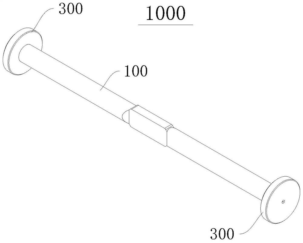
[0061] Please refer to figure 1 and figure 2 , this embodiment provides a tension holding device 1000, which is suitable for vibrating wire equipment, tension piles, etc., which can keep the tension of the tension string 200 passing through the above equipment stable.

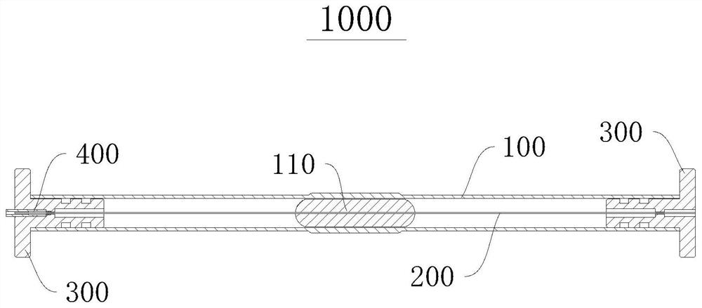
[0062] The tension holding device 1000 includes: a protective cover 100 , a base 300 and a fixing assembly 400 . Both ends of the protective cover 100 are fitted with a base 300 , and the string 200 can be accommodated in the protective cover 100 and pass through the base 300 . The fixing assembly 400 fixes the pulling string 200 to the base 300 so that the pulling force of the pulling string 200 remains unchanged.

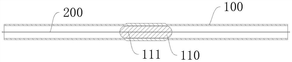
[0063] Please refer to image 3 , the protective sleeve 100 is in the shape of a cylinder as a whole, and the inner cavity of the protective sleeve 100 is a hollow pipe that penetrates the protective sleeve 100 along the axial direction thereof. The pull string 200 is accommodated in the inner...

Embodiment 2

[0116] Please refer to Figure 16 , and combine Figure 15 , This embodiment provides a vibrating wire device 2000 , and the vibrating wire device 2000 includes a pulling wire 200 , an electromagnetic component (not shown) and a tension holding device 1000 .

[0117] The pulling string 200 of the vibrating wire device 2000 is fixed by the pulling force holding device 1000. The pulling string 200 is arranged in the protective cover 100. 410 and reinforcement 420 are fixed.

[0118] The electromagnetic components are installed in the hollow pipe of the protective cover to detect the change of the vibration frequency of the pulling string 200 .

[0119] The vibrating wire device 2000 uses the tension holding device 1000 to fix the pulling string, and the pulling force of the pulling string remains unchanged at the initial preset value, which greatly improves the accuracy of measurement and induction, and has more stable, reliable performance and higher accuracy.

[0120] It ca...

Embodiment 3

[0122] Please refer to Figure 17 , this embodiment provides a tensile force holding structure 3000 , and the tensile force holding structure 3000 includes the base 300 , the connecting member 410 and the reinforcing member 420 of the tensile force holding device 1000 in the first embodiment.

[0123] The base 300 can be used to connect with other objects, such as being mounted on a concrete pile. In this case, when the base 300 is matched with the fixing assembly 400, one end of the pulling string 200 can be fixed, and the other end of the pulling string 200 can be fixed. It can be used to connect with other objects that need to be tensioned, and the tension retention structure 3000 can continuously provide stable tension to other objects.

[0124] The tension retaining structure 3000 can be applied to tension and reinforce electric piles, and can be used to tension electric wires, but is not limited thereto.

[0125] Please refer to Figure 18 , in a variation of this embo...


PUM


Abstract

A tension holding structure, a tension holding device and a vibrating wire device relate to the technical field of tension holding. The tension holding structure includes a base, connectors and reinforcements; the base is provided with a through hollow channel, and a stopper is arranged in the hollow channel; the connector is accommodated in the hollow channel; the reinforcement is accommodated in the hollow channel and is connected with the The connecting piece is interference fit, so as to press the connecting piece against the stopper. Both tension holding devices and vibrating wire devices include tension holding structures. It can solve the technical problem that the pulling force of the pulling string becomes smaller after the installation is completed in the prior art existing in the pulling force maintaining device of the pulling string in the cavity.

Description

【Technical field】 [0001] The present invention relates to the technical field of tension retention, in particular, to a tension retention structure, a tension retention device and a vibrating wire device. 【Background technique】 [0002] When installing the tension holding device in the cavity, it is necessary to use a tension gauge to accurately control the tension of the tension. corresponding pulling force. However, during the installation process of the existing intra-cavity string-pulling force retaining device, after the installation is completed, the string-pulling force often becomes smaller, resulting in the actual string-pulling force being less than the set value. [0003] In view of this, this application is hereby made. [Content of the invention] [0004] In order to solve the technical problem in the prior art that the pulling force of the string pulling force in the cavity becomes smaller after installation, the embodiments of the present invention provide ...

Claims


Application Information

Patent Timeline
Patent Type & Authority Patents(China)
IPC IPC(8): G01H11/00G01H13/00
CPCG01H11/00G01H13/00
Inventor 徐廷端
Owner 厦门邦创信息技术有限公司
Why Eureka
Try Eureka