[0030] Example
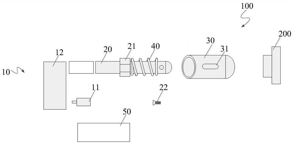
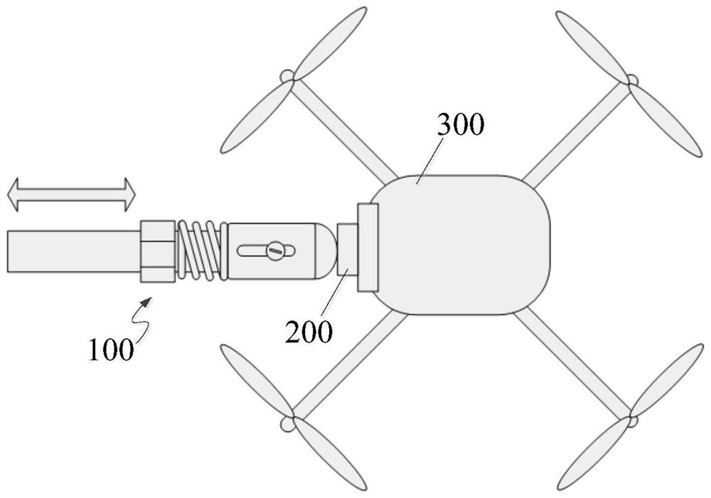
[0031] reference figure 1 , 2 The structure of the touch device 100 shown and the application scenario, the embodiment of the present invention provides a touch apparatus 100, which comprises: a power source 10 that provides power for touch device 100.
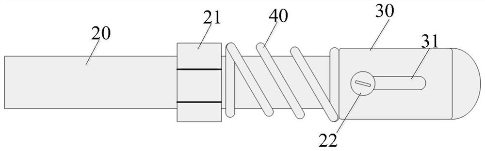
[0032] The touch device 100 also includes a push rod 20, and the power source 10 is connected to the first end of the push rod 20, and the drive push rod 20 is reciprocated. Alternatively, the push rod 20 is a straight rod, and the power source 10 drives the push rod 20 to reciprocate in its rod extension direction, specifically, the push rod 20 moves in the direction of the button device 200 and the remote button device 200.
[0033] The touch device 100 also includes a pressing cap 30 that is set to the second end of the push rod 20 in the pressing cap 30, and the top of the compression cap 30 is used to press the button apparatus 200, and the cap body is pressed on the cap 30. 31. Pressing the cap 30 for contact with the button device 200 of the drone 300, and the top may be processed into various shapes according to the shape of the button device 200, optionally, the top of the pressing cap 30 can be semi-circular, square, spherical or For a rod.
[0034] Among them, a finitex structure 21 is provided on the rod body on the rod body, and a sliding portion 22 is provided on the rod body between the limit structure 21 and the second end of the push rod 20. The sliding portion 22 cooperates with the slide 31 to reciprocate along the slide 31. An elastic member 40 is provided between the pressing cap 30 and the limit structure 21.
[0035] Specifically, the sliding portion 22 is disposed in the slide 31, and the sliding portion 22 can be flexibly moved within the scope of the slide 31, optionally, slide 31 is a straight bar or groove. It should be noted that when the push cap 30 is not contacting the button device 200, the second end of the push rod 20 has a buffer space between the top inner wall of the pressing cap 30, which is greater than or equal to the length of the slide 31.
[0036] Such as figure 1 , 2 , 3, the elastic member 40 is spring, and both ends of the spring are in contact with the limit structure 21 and the pressing cap 30, respectively. Among them, the spring ends of the spring are brought to the bottom and the limit structure 21 of the pressing cap 30 close to the pressing cap 30.
[0037] Optional, such as figure 1 , 2 , 3, the spring is fixed to the limit structure 21 or pressing the cap 30.
[0038] Wherein, when the pressing cap 30 is not in contact with the button device 200, the elastic member 40 applies an elastic pressure on the limit structure 21 and the pressing cap 30, at which, the sliding portion 22 is located at the bottom end of the slide 31, and press the cap 30 and the button device. After contact, the push rod 20 moves the elastic member 40 to be compressed, and the sliding portion 22 moves in the tide of the slide 31 toward the top of the slide 31. When the sliding portion 22 of the push rod 20 is moved within the slide 31, the trigger button device 200 is successfully opened, and the distance between the sliding portion 22 to the top of the slide 31 is a buffer distance.
[0039] Such as figure 1 , 2 However, shown, the position of the limit structure 21 can be adjusted on the push rod 20 to adjust the elastic member 40 in the initial state. Alternatively, the limit structure 21 is a nut in the rod body, and the nut can be displaced along the rod by threaded threads, thereby changing the elastic member 40.
[0040] Such as figure 1 The touch device 100 also includes a controller 50, and the controller 50 is configured to control the overall movement of the touch device 100.
[0041] The power source 10 includes a drive motor 11 and a transmission mechanism 12. The drive motor 11 drives the transmission mechanism 12 to drive the push rod 20 to reciprocate.
[0042] The controller 50 is connected to the drive motor 11 for controlling the operational state of the drive motor 11.
[0043] Such as figure 1 , 2 3, the touch device 100 also includes: an encoder, an encoder for measuring the rotational stroke of the drive motor 11. Wherein, the movement distance of the push rod 20 is proportional to the rotation stroke of the drive motor 11. That is, the moving distance of the push rod 20 can be calculated by the rotation stroke of the drive motor 11.
[0044] Such as figure 1 , 2 , 3, the sliding portion 22 is detachable between the pusher 20. Alternatively, the sliding portion 22 is a fixed screw, and a screw hole is provided on the rod body of the push rod 20 for fixing the fixed screw.
[0045] Alternatively, in another embodiment of the present invention, a sliding portion is provided on the inner wall of the cap body of the compression cap 30. The finiteral structure 21 is provided on the push rod body, and there is a slide on the rod body between the limit structure 21 and the second end of the push rod 20. The sliding portion is fitted with the slide, and the pressing cap 30 is reciprocated along the slide. An elastic member 40 is provided between the pressing cap 30 and the limit structure 21.
[0046] Such as figure 1 , 2 , 3, 4, according to an embodiment of the present invention, a adjustment method of touching apparatus 100, including:
[0047] Step 1: Set the first initial speed of the drive motor 11 is V 0 The first acceleration is a 0 The first mobile time is T 0 The drive motor 11 drives the pusher 20 to move from the initial position to the button device 200.
[0048] Step 2: Adjust the first initial speed of the drive motor 11 is V 0 The first acceleration is a 0 The first mobile time is T 0 At least one of the medium, until the top of the pressing cap 30 is just in contact with the button device 200, and the first rotation stroke S of the driving motor 11 is recorded. 0 At this time, the second initial speed of the drive motor 11 is V. 1. Where V 1 = V 0 + a 0 t 0 , First rotation stroke S 0 For the first mobile time is T 0 The rotation stroke of the corresponding drive motor 11 is driven.
[0049] Step 3: Set the second acceleration of the drive motor 11 is a 1 , Second mobile time is T 1 The drive motor 11 continues to drive the push rod 20 to move in the direction of the button device 200.
[0050] Step 4: Adjust the second acceleration of the drive motor 11 is A 1 , Second mobile time is T 1 At least one amount, until the pressing cap 30 is triggered, the button device 200 is successfully pressed, and the second rotation stroke S of the driving motor 11 is recorded. 1 At this time, the third initial speed of the drive motor 11 is V. 2. Where V 2 = V 1 + a 1 t 1 , Second rotation stroke S 1 For the second mobile time is T 1 The rotation stroke of the corresponding drive motor 11 is driven.
[0051] Step 5: Set the third acceleration of the drive motor 11 is a 2 , The third mobile time is T 2 The push rod 20 is still moving in the direction of the button device 200 to move.
[0052] Step 6: Adjust the third acceleration of the drive motor 11 is A 2 , The third mobile time is T 2 At least one amount of the medium until the speed V of the drive motor 11 3 When it is 0, the sliding portion 22 at this time does not reach the slide 31 close to the button device 200 or just reacly reaches the slide 31 close to the button device 200, the third rotation stroke S of the driving motor 11 is recorded. 2. Among them, the third rotation stroke S 2 For the third mobile time is T 2 The rotation stroke of the corresponding drive motor 11 is driven.
[0053] Optionally, the adjustment method also includes: setting the fourth acceleration of the drive motor 11 is a 3 , Fourth mobile time is T 3 The drive motor 11 drives the push rod 20 to move toward the distance of the button device 200. Adjust the fourth acceleration of the drive motor 11 is a 3 , Fourth mobile time is T 3 At least one of the medium, until the top end detachment button apparatus 200 of the clip 30, the fourth rotation stroke S of the driving motor 11 is recorded 3. Among them, the fourth rotation stroke S 3 For the fourth mobile time is T 3 The rotation stroke of the corresponding drive motor 11 is driven.
[0054] Optionally, in the adjustment method, the first rotation stroke S 0 , Second rotation stroke S 1 , The third rotation stroke S 2 , Fourth rotation stroke S 3 The controller 50 is stored, as the reference data of the touch device 100 and the button device 200.
[0055] Such as Figure 5 As shown, after the controller 50 receives the pressing command of the host computer, the speed, acceleration, and rotation stroke of the drive motor 11 are sequentially controlled by the controller 50. One step is an error, for example, if the specified location is not met, the entire pressing process is considered to fail, and the unfinished pressing action is reported to the host computer. If all orders are completed, the end messages are reported to the host computer. Among them, the method of determining the designated position is used as the mobile time as the touch device 100 reaches the designated position.