Automatic continuous punching device for metal plate

A punching device, metal plate technology, applied in the direction of feeding device, storage device, positioning device, etc., can solve the problems of general stability, high cost, large manpower, etc., to improve stability and service life, improve stability , the effect of improving usability

Inactive Publication Date: 2021-07-13
深圳市迅成科技有限公司
View PDF0 Cites 5 Cited by
  • Summary
  • Abstract
  • Description
  • Claims
  • Application Information

AI Technical Summary

Problems solved by technology

[0003] For the drilling of metal plates, manual hand-held electric drills are generally used for drilling, which consumes a lot of manpower, and the drilling efficiency is not high, and it is not suitable for continuous drilling in batches. Therefore, automatic continuous drilling has appeared on the market. device, while the existing continuous dr

Method used


Image

  • Automatic continuous punching device for metal plate
  • Automatic continuous punching device for metal plate
  • Automatic continuous punching device for metal plate

Examples


Embodiment Construction

[0022] The present invention is described in further detail now in conjunction with accompanying drawing. These drawings are all simplified schematic diagrams, which only illustrate the basic structure of the present invention in a schematic manner, so they only show the configurations related to the present invention.

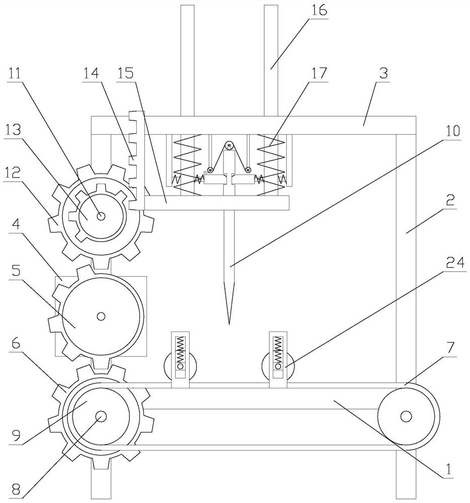
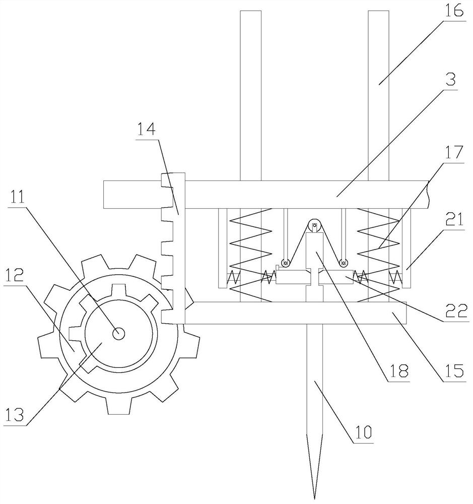
[0023] Such as figure 1 As shown, an automatic continuous punching device for metal plates includes a base 1, a support rod 2, a cross bar 3, a driving mechanism, a transmission mechanism and a punching mechanism. There are two support rods 2 and two support rods. Rods 2 are respectively arranged at both ends of the base 1, the crossbar 3 is arranged above the base 1 through the pole 2, the driving mechanism is arranged on the pole 2, the transmission mechanism is arranged on the base 1, and the punching mechanism is arranged on the base 1. The hole mechanism is arranged above the transmission mechanism;

[0024] Place the workpiece on the conveying mechanis...


PUM


Abstract

The invention relates to an automatic continuous punching device for a metal plate. The automatic continuous punching device for the metal plate comprises a base, a supporting rod, a cross rod, a driving mechanism, a conveying mechanism and a punching mechanism, the conveying mechanism is arranged on the base, and the punching mechanism is arranged above the conveying mechanism. According to the automatic continuous punching device for the metal plate, the conveying mechanism and the punching mechanism are driven by the driving mechanism to intermittently operate, continuous punching of workpieces is achieved, and compared with an existing punching device, the automatic continuous punching device has the advantages that operation of the conveying mechanism and the punching mechanism is achieved through one output end, energy is saved, meanwhile, linkage is adopted by the conveying mechanism and the punching mechanism, online punching of the workpieces is achieved, the linkage adopts a pure mechanical structure, the stability of the device is improved, and the service life of the device is prolonged. Compared with an existing punching mechanism, the mechanism adopts the mechanical structure to replace air cylinder driving, the stability is improved, meanwhile, the movement of a movable rod is buffered and positioned through a positioning assembly, the device runs more stably, and the practicability is improved.

Description

technical field [0001] The invention relates to an automatic continuous punching device for metal plates. Background technique [0002] A metal plate is a plate made of a metal material and is widely used in industrial production. When the metal plate is used, it usually needs to be punched. [0003] For the drilling of metal plates, manual hand-held electric drills are generally used for drilling, which consumes a lot of manpower, and the drilling efficiency is not high, and it is not suitable for continuous drilling in batches. Therefore, automatic continuous drilling has appeared on the market. device, while the existing continuous drilling device generally requires multiple output ends to be driven separately for the movement and punching of the workpiece, which consumes a lot of energy and costs high, and the existing drilling device generally uses a cylinder to drive the drill bit to move, Compared with the driving method of purely mechanical structure, the stability ...

Claims


Application Information

Patent Timeline
IPC IPC(8): B21D28/34B21D28/26B21D43/00B21D43/12
CPCB21D28/26B21D28/34B21D43/003B21D43/12
Inventor 张晓奎
Owner 深圳市迅成科技有限公司
Why Eureka
Try Eureka