A cavitation venturi

A Venturi tube and cavitation technology, applied in the field of aerodynamics, can solve the problems of large fluid pressure loss and easy jamming of the valve core in the throat of the Venturi tube shell, etc., to reduce pressure loss and reduce jamming in the throat Part and can not move the spool, to ensure the effect of stable work

Active Publication Date: 2022-07-22
BEIHANG UNIV
View PDF16 Cites 0 Cited by
  • Summary
  • Abstract
  • Description
  • Claims
  • Application Information

AI Technical Summary

Problems solved by technology

[0007] The purpose of the present invention is to provide a cavitation venturi tube to solve the problems in the prior art that the fluid pressure loss in the cavitation venturi tube is relatively large and the valve core is easily stuck in the throat of the venturi tube shell. Problem; Many technical effects that the preferred technical solution in the many technical solutions provided by the present invention can produce are set forth in detail below

Method used


Image

  • A cavitation venturi
  • A cavitation venturi
  • A cavitation venturi

Examples


Embodiment 1

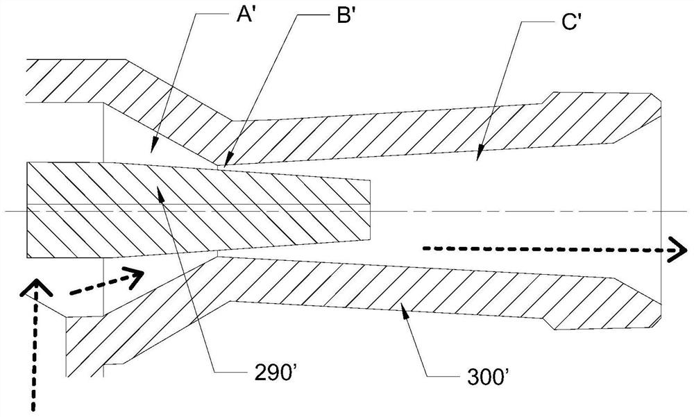
[0051] For the above issues, see figure 2 image 3 and Figure 4 , Figure 8 As shown, this embodiment provides a cavitation venturi, including a valve core 290 and a venturi casing 300, wherein: the flow channel in the venturi casing 300 includes constricted sections that communicate in sequence along the fluid flow direction A, the throat B and the expansion section C, the valve core 290 is movably arranged to cooperate with the throat B to adjust the flow rate of the fluid; the valve core 290 has a conical part, and the conical part extends from the expansion section C through the throat to the contraction section A, and the radial section of the tapered portion tends to decrease along the direction from the expansion section C to the contraction section A;

[0052] Among them, the "contraction section" refers to the radial cross-sectional area of ​​the inner profile surface of the venturi casing 300 gradually shrinking along the fluid flow direction, and the "expansion...

specific Embodiment approach

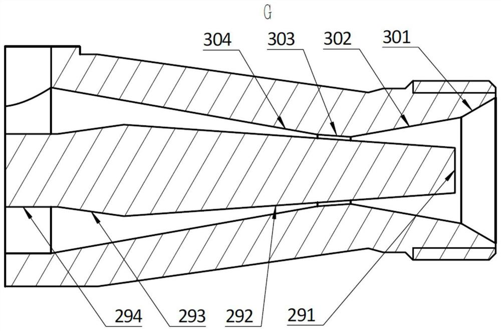
[0056] In this embodiment, the specific structure of the valve core 290 is as follows: see Figure 2-Figure 4 shown, see image 3 , the outer wall surface of the valve core 290 includes a needle cone surface 292, a needle cone shrinking surface 293 and a cylindrical surface 294 which are sequentially connected along its axial direction. The minimum flow section of the flow channel is formed; the part where the cylindrical surface 294 is located is connected with a driving mechanism used to drive the valve core 290 to move, and the diameter of the needle-cone constricting surface 293 decreases along the direction from the needle-cone surface 292 to the cylindrical surface 294. Reduce the radial section of the cylindrical surface 294; preferably, the diameter of the conical constriction surface 293 gradually decreases along the direction from the conical surface 292 to the cylindrical surface 294; the end of the valve core 290 close to the fluid inlet is also formed with a trunc...

Embodiment 2

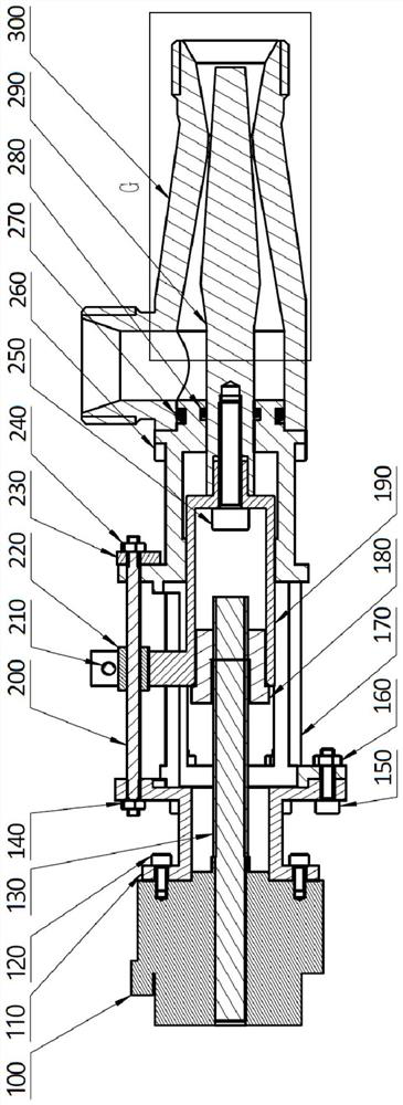
[0082] This embodiment is an improvement on the basis of the above-mentioned first embodiment. This embodiment provides a specific implementation of a driving mechanism, see figure 2 , Figure 4 , Figure 5 , Image 6 As shown, the cavitation venturi also includes a drive mechanism, and the drive mechanism includes a drive device, a lead screw 130, a lead screw nut 180 and a drive block 190, wherein: the output shaft of the drive device is connected with the lead screw 130, and the lead screw 130 is connected to the lead screw 130. The lead screw nut 180 is threadedly connected, one end of the driving block 190 is fixedly connected to the lead screw nut 180, and the other end is fixedly connected to the valve core 290. When the driving device rotates forwardly and reversely, the lead screw 130 and the lead screw nut 180 can cooperate with each other. The structure drives the driving block 190 and the valve core 290 to reciprocate and linearly move in the axial direction.

...


PUM


Abstract

The invention provides a cavitation venturi, which relates to the technical field of aerodynamics and solves the technical problems that the fluid pressure loss in the cavitation venturi is relatively large and the valve core is easily stuck in the throat of the venturi casing. The cavitation venturi includes a valve core and a venturi shell, the flow channel in the venturi shell includes a constriction section, a throat and an expansion section which are sequentially communicated along the fluid flow direction, and the valve core is movably arranged to be connected with the throat. The valve core has a cone-shaped part, the cone-shaped part extends from the expansion section to the contraction section through the throat, and the radial section of the cone-shaped section tends to decrease along the direction from the expansion section to the contraction section. In the cavitation venturi of the invention, the conical part of the valve core extends from the expansion section to the contraction section through the throat, which reduces the outlet angle of the expansion section, improves the pressure recovery characteristics of the adjustable Venturi, and reduces the pressure loss . When the valve core opening is at 0, it can reduce the situation that the valve core is stuck in the throat and cannot move the valve core, and ensures the stable operation of the valve core.

Description

technical field [0001] The invention relates to the technical field of aerodynamics, in particular to a cavitation venturi. Background technique [0002] Adjustable cavitation venturi is an important flow regulating element with excellent regulating performance. It is widely used in variable thrust liquid rocket engines. It can precisely control the component ratio of propellants and improve the thrust accuracy of variable thrust rocket engines. . [0003] Existing adjustable cavitation venturis mainly consist of venturi housing and valve core, see figure 1 shown, figure 1 It is a schematic cross-sectional structure diagram of the valve core and the venturi casing in the prior art, the arrow direction in the figure represents the flow direction of the fluid; the end of the valve core extending into the venturi casing is a cone-shaped structure. The venturi housing has a flow passage that allows the fluid to pass through the side of the venturi housing and into the rear e...

Claims


Application Information

Patent Timeline
Patent Type & Authority Patents(China)
IPC IPC(8): G05D7/00
CPCG05D7/00
Inventor 张源俊谭广田辉蔡国飙卢裕东陈瑞凯
Owner BEIHANG UNIV
Why Eureka
Try Eureka