Optical lens assembly

A technology of optical lenses and components, applied in optical components, optics, instruments, etc., can solve problems such as the difficulty of effectively focusing light beams, and achieve the effects of smaller spherical aberration and astigmatism, improved imaging brightness, and reduced exit angles

Active Publication Date: 2012-06-20
BYD SEMICON CO LTD
View PDF0 Cites 0 Cited by
  • Summary
  • Abstract
  • Description
  • Claims
  • Application Information

AI Technical Summary

Problems solved by technology

However, in optical design, a large aperture also means that it is more difficult for the beam to focus effectively, more stray light and comprehensive aberrations. How to effectively eliminate aberrations while ensuring a large amount of light to obtain a good imaging effect and maximize the Reduce production costs, have good processability, and adapt to industrial mass production will be the difficulty and focus of optical design

Method used


Image

  • Optical lens assembly
  • Optical lens assembly
  • Optical lens assembly

Examples


Embodiment 1

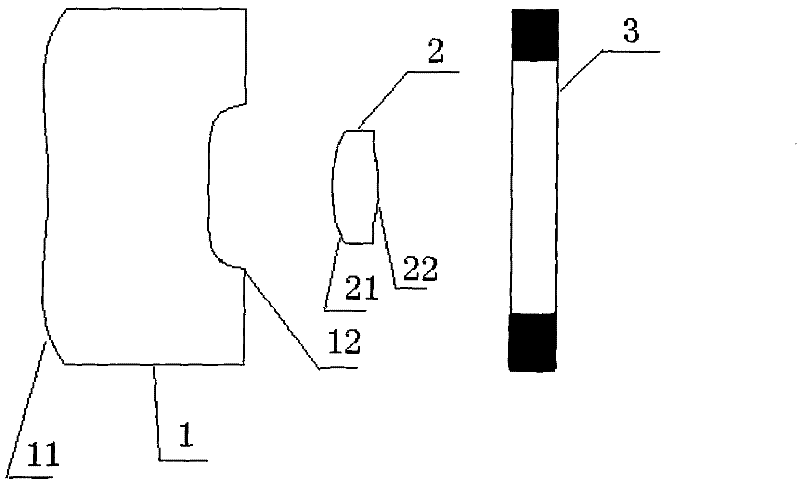
[0019] Such as figure 1 As shown, an optical lens assembly provided by an embodiment of the present invention includes a lens group and a fixed diaphragm 3. The lens group includes a first lens 1 and a second lens 2 coaxially and sequentially arranged from the object side to the image side The first lens 1 has a first surface 11 facing the object side and a second surface 12 facing the image side, and the second lens 2 has a third surface 21 facing the object side and a fourth surface 22 facing the image side; The first surface 11 and the second surface 12 are both aspherical; the first surface 11 is a convex surface, and the second surface 12 is a concave surface; the third surface 21 and the fourth surface 22 are both aspherical; the third surface 21 is a convex surface, and the fourth surface 22 is a convex surface; the first lens 1 has a negative refractive power as a whole, and the second lens 2 has a positive refractive power as a whole. The fixed diaphragm 3 is located o...

Embodiment 2

[0030] figure 2 It is a schematic diagram of the second embodiment of the optical lens assembly of the present invention, refer to figure 2 , The second embodiment of the present invention is proposed. This embodiment further proposes the following related parameters of the lens assembly based on the first embodiment:

[0031] Lens parameters:

[0032] Types of

Radius of curvature (R)

Quadric coefficient (k)

Thickness (dmm)

First surface

8.074533

-61.72694

2.80

Second surface

-5.721327

13.73578

2.05

Third surface

-9.945894

91.41678

0.9

Fourth surface

-1.92936

-2.27452

0.1

Front surface of filter

0.9

Back surface of filter

2.0

Image surface

0

[0033] Aspheric coefficient:

[0034] The first surface: (aspherical)

[0035] a 1 : -0.12711201

[0036] a 2 : 0.022288763

[0037] a 3 : -0.001871822

[0038] a 4 : 6.199145e-005

[0039] a 5 : 2.8747284e-005

[0040] a 6 : -5.9170367e-006

[0041] a 7 : 4.9221476e-007

[0042] a 8 : -1.5570923e-0...

Embodiment 3

[0076] Image 6 It is a schematic diagram of the second embodiment of the optical lens assembly of the present invention, refer to Image 6 , The second embodiment of the present invention is proposed. This embodiment further proposes the following related parameters of the lens assembly based on the first embodiment:

[0077] Lens parameters:

[0078] Types of

Radius of curvature (R)

Quadric coefficient (k)

Thickness (dmm)

First surface

9.226689

-78.91152

2.87

Second surface

-5.647945

13.8713

2

Third surface

-7.961955

33.04664

0.78

Fourth surface

-1.713565

-1.78347

0.1

Front surface of filter

0.9

Back surface of filter

2.1

Image surface

0

[0079] Aspheric coefficient:

[0080] The first surface (aspherical surface):

[0081] a 1 : -0.13239387

[0082] a 2 : 0.020306834

[0083] a 3 : -0.0012555407

[0084] a 4 :-4.8945981e-005

[0085] a 5 : 3.6343123e-005

[0086] a 6 : -5.6776908e-006

[0087] a 7 : 4.2806789e-007

[0088] a 8 : -1.2934...


PUM

PropertyMeasurementUnit
refractive indexaaaaaaaaaa

Abstract

The invention relates to the field of optics and provides an optical lens assembly. The optical lens assembly comprises a first lens and a second lens which are coaxial and are arranged from an object side to an image side in turn, and a fixed diaphragm which is positioned on the rear of the second lens, wherein the first lens is provided with a first convex and aspherical surface which faces theobject side and a second concave and aspherical surface which faces the image side; and the second lens is provided with a third convex and aspherical surface which faces the object side and a fourthconvex and aspherical surface which faces the image side. The optical lens assembly meets the following conditions that: L / f is more than 3.3, f1 is less than 0 and f2 is more than 0, wherein f is aneffective focal distance value of the whole optical lens assembly; L is the total length of an optical system; f1 is an effective focal distance value of the first lens and f2 is an effective focal distance value of the second lens. The optical lens assembly is provided with only two lenses with negative and positive diopters, can collect more edge rays as possible, effectively improves the imagesurface brightness, reduces an emergence angle of a principal ray of the system and well corrects the off-axis aberration.

Description

Technical field [0001] The invention relates to an optical device, in particular to an optical lens assembly. Background technique [0002] In the digital imaging equipment, the optical imaging lens is a particularly important component, and the image quality of the lens directly determines the imaging performance of the digital imaging equipment. Existing optical imaging lens products tend to focus on excellent imaging quality and pay less attention to the amount of light received. The default clear aperture in the industry is F.NO=2.8. With the continuous updating of digital products at the same time, the development of sensor technology has forced continuous breakthroughs in lens design to achieve greater light flux in order to achieve better results in PC camera and monitor material applications. Therefore, lens design with large apertures such as F.NO 2.0 and 1.8 will receive more and more attention. However, in optical design, a large diaphragm aperture also means that th...

Claims


Application Information

Patent Timeline
Patent Type & Authority Patents(China)
IPC IPC(8): G02B13/00G02B13/18G02B1/00G02B1/04
Inventor 姜莉莉
Owner BYD SEMICON CO LTD
Why Eureka
Try Eureka