Optical lens component

An optical lens and component technology, applied in optical components, optics, filters, etc., can solve the problems of not being light, thin, short, high production cost, increasing the size of the lens, etc., and achieve good optical performance, easy processing, and reduced size. The effect of the exit angle

Active Publication Date: 2012-03-07
BYD SEMICON CO LTD
View PDF8 Cites 0 Cited by
  • Summary
  • Abstract
  • Description
  • Claims
  • Application Information

AI Technical Summary

Problems solved by technology

Especially in the lens module with more than one million pixels, in order to ensure high imaging quality and brightness and achieve a sufficient field of view, the digital imaging system needs a large space to inflect light, and the method of increasing the number of lenses is often used to correct Aberration, improve imaging quality; the length of this product is far from meeting the requirements of thinness and shortness, on the one hand, it increases the lens volume, on the other hand, it leads to higher production costs

Method used


Image

  • Optical lens component
  • Optical lens component
  • Optical lens component

Examples


Embodiment 1

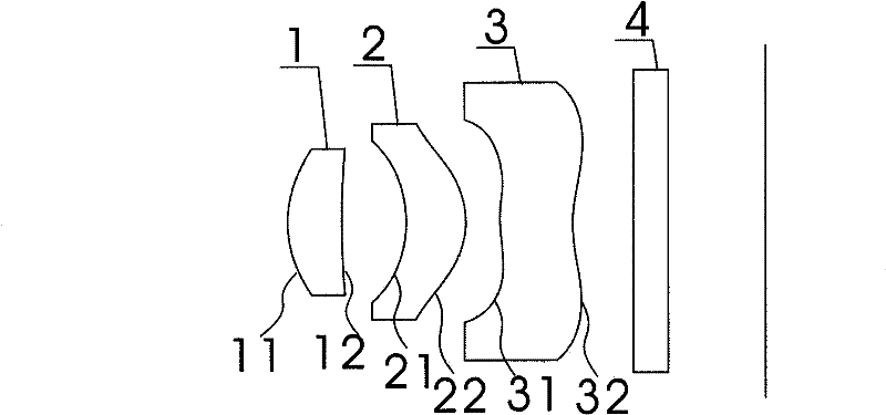
[0017] Such as figure 1 As shown, an optical lens assembly provided by an embodiment of the present invention includes a fixed diaphragm, a lens group and a filter, and the lens group includes coaxial plastic first lenses arranged in sequence from the object side to the image side 1. The second lens 2 and the third lens 3, the fixed diaphragm is located in front of the first lens, and the optical filter 4 is located behind the third lens 3; the optical filter 4 has a front surface facing the object side and a front surface facing the The rear surface of the image side, the first lens 1 has a first surface 11 facing the object side and a second surface 12 facing the image side, and the second lens 2 has a third surface 21 facing the object side and a fourth surface facing the image side 22. The third lens 3 has a fifth surface 31 facing the object side and a sixth surface 32 facing the image side; the above-mentioned first and second surfaces are spherical or aspherical; the t...

Embodiment 2

[0034] In the second embodiment provided by the present invention, the first surface and the second surface of the first lens are both spherical. On the basis of the first embodiment, the related parameters of the lens assembly are further proposed as follows:

[0035] Lens parameters:

[0036] Types of Radius of curvature (R) Quadratic coefficient (k) Thickness (dmm) first surface 1.594564 0 0.46 second surface 7.448407 0 0.46 third surface -0.9014985 0.558048 0.51

[0037] fourth surface -0.77080053 -3.646588 0.03 fifth surface 2.285779 -0.3571741 0.61 sixth surface 1.262574 -2.743714 0.15 Filter Front Surface 0.3 Filter rear surface 0.582 Image surface 0

[0038] Aspheric Coefficient:

[0039] Types of a2 a4 a6 a8 a10 a12 third surface -0.074 51354 0.042 01622 -1.22 547 ...

Embodiment 3

[0045] In the third embodiment provided by the present invention, the first surface and the second surface of the first lens are both aspherical. On the basis of the first embodiment, the related parameters of the lens assembly are further proposed as follows:

[0046] Lens parameters:

[0047] Types of Radius of curvature (R) Quadratic coefficient (k) Thickness (dmm) first surface 1.157693 -0.001725295 0.46 second surface 5.45727 21.00672 0.55 third surface -1.0005 -1.655477 0.54 fourth surface -0.8397087 -4.294348 0.03 fifth surface 3.904352 70.69126 0.66 sixth surface 1.347997 11.08139 0.12 Filter Front Surface 0.3 Filter rear surface 0.76 Image surface 0

[0048] Aspherical Coefficient:

[0049] Types of a2 a4 a6 a8 a10 a12 first surface 0.005 1962324 -0.013 577327 0.26 202436 -0...


PUM

PropertyMeasurementUnit
refractive indexaaaaaaaaaa

Abstract

The invention relates to an optical lens component which comprises a fixed light diaphragm, a lens group and a light filter; the lens group comprises a first plastic positive lens, a second positive lens and a third negative lens which are coaxial and are sequentially lined from the object side to the image side; the first lens is provided with a first surface and a second surface, the second lens is provided with a third surface and a fourth surface, and the third lens is provided with a fifth surface and a sixth surface; the fixed light diaphragm is arranged before the first lens, and the light filter is arranged behind the third lens; the first surface and the second surface are spherical or non-spherical; the third surface, the fourth surface, the fifth surface and the sixth surface are non-spherical; the first surface is an arc shape which protrudes to the object side, and the second surface is a smooth arc-shaped concave shape relative to one side of the image side; the third surface is the arc-shaped concave shape relative to one side of the object side, and the fourth surface is an arc shape which protrudes to the image side; and the fifth surface and the sixth surface arein an M shape, the center of the fifth surface protrudes to one side of the object side, and the center of the sixth surface protrudes to one side of the object side.

Description

Technical field [0001] The invention involves optical devices and specifically involves an optical lens component. Background technique [0002] In digital imaging devices, optical imaging lenses are particularly important components. The image of the lens directly determines the imaging performance of the digital imaging device.Digital products are constantly updated, and it is increasingly developing in the direction of light and light and short, so it has a higher and higher requirements for optical lenses equipped in digital imaging devices.Especially in the lens module above millions of pixels, in order to ensure high imaging quality and brightness, to achieve sufficient viewing angle, the digital imaging system requires a large space to fold the light.Poor elephants and improve the quality of imaging; the length of this product does not meet the requirements of light and light and short, on the one hand, the lens volume is increased, and on the other hand, the production co...

Claims


Application Information

Patent Timeline
Patent Type & Authority Patents(China)
IPC IPC(8): G02B7/00G02B7/02G02B1/04G02B9/12G02B13/18G02B5/20
Inventor 杨志
Owner BYD SEMICON CO LTD
Why Eureka
Try Eureka