Dual ring ejector

An ejector and ring-type technology, applied in the field of double-ring ejector, can solve the problem of unfavorable installation and use, inability to achieve simultaneous injection and blending of two secondary fluids, and low contact rate between primary fluid and secondary fluid and low entrainment efficiency. And other issues

Inactive Publication Date: 2012-09-19
韩铁夫
View PDF8 Cites 12 Cited by
  • Summary
  • Abstract
  • Description
  • Claims
  • Application Information

AI Technical Summary

Problems solved by technology

[0005] 1. The existing injectors mainly rely on the turbulent diffusion of the jet in the long stroke of the mixing tube to make the main fluid and the secondary fluid mix with each other. The turbulent diffusion of the jet needs a development and strengthening in the mixing tube. Therefore, the injector must have a slender mixing tube (or mixing diffuser tube), and a large-diameter injector needs a large-diameter mixing tube. The larger the diameter, the more difficult it is to form uniform mixing by jet turbulent diffusion. If the body and the entrained secondary fluid can be fully mixed in the mixing tube for mass transfer and pressure equalization, the length of the mixing tube needs to be greatly increased, resulting in the axial size and space of the existing ejector, especially the large-scale single-tube injector. Disadvantages of space occupation and excessive weight
This is very unfavorable for installation and use in many occasions that require small volume and light load
[0006] 2. For single-pipe injectors or jet pumps with large passage and flow rates, a large passage through the mixing pipe is required. In order to achieve the purpose of pumping the secondary fluid well (that is, to achieve a large injection ratio or a high mixed output pressure), it is necessary to maintain a certain Throat surface ratio (section ratio of the mixing tube to the main fluid nozzle) so that the free jet of the main fluid can diffuse and fill the mixing tube after reaching a certain opening, resulting in a piston

Method used


Image

  • Dual ring ejector
  • Dual ring ejector
  • Dual ring ejector

Examples


Embodiment 1

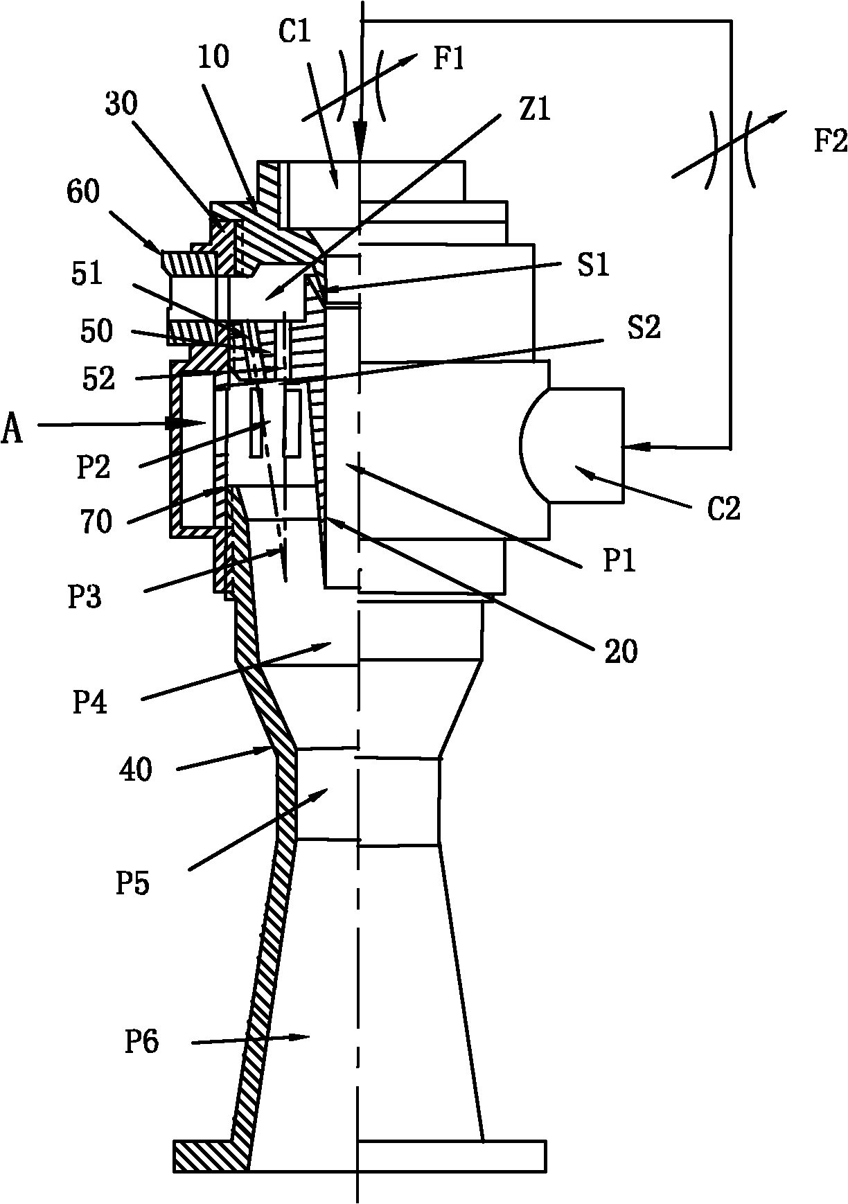
[0046] The first embodiment of the double-ring injector of the present invention is an injector that uses a primary fluid to guide two secondary fluids entering from two secondary fluid inlets, and outputs a mixed fluid. see figure 1 , the present embodiment is provided with an inner ring injector assembly and an outer ring injector assembly along the central axis, and the outer ring injector assembly is provided with a total mixing output pipe backward along the central axis. The inner ring injector assembly is coaxially fixed and sleeved in the outer ring injector assembly.

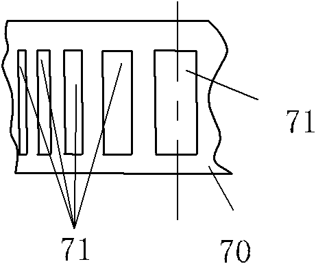
[0047] The inner ring injector assembly is provided with a central secondary fluid inlet sleeve 10 and an inner tube 20 , both of which are coaxial and the inner tube 20 is located at the outlet end of the central secondary fluid inlet sleeve 10 . The caliber of the inlet C1 of the central secondary fluid inlet sleeve 10 is larger than the outlet caliber, and the tapered mouth at the rear end of the ce...

Embodiment 2

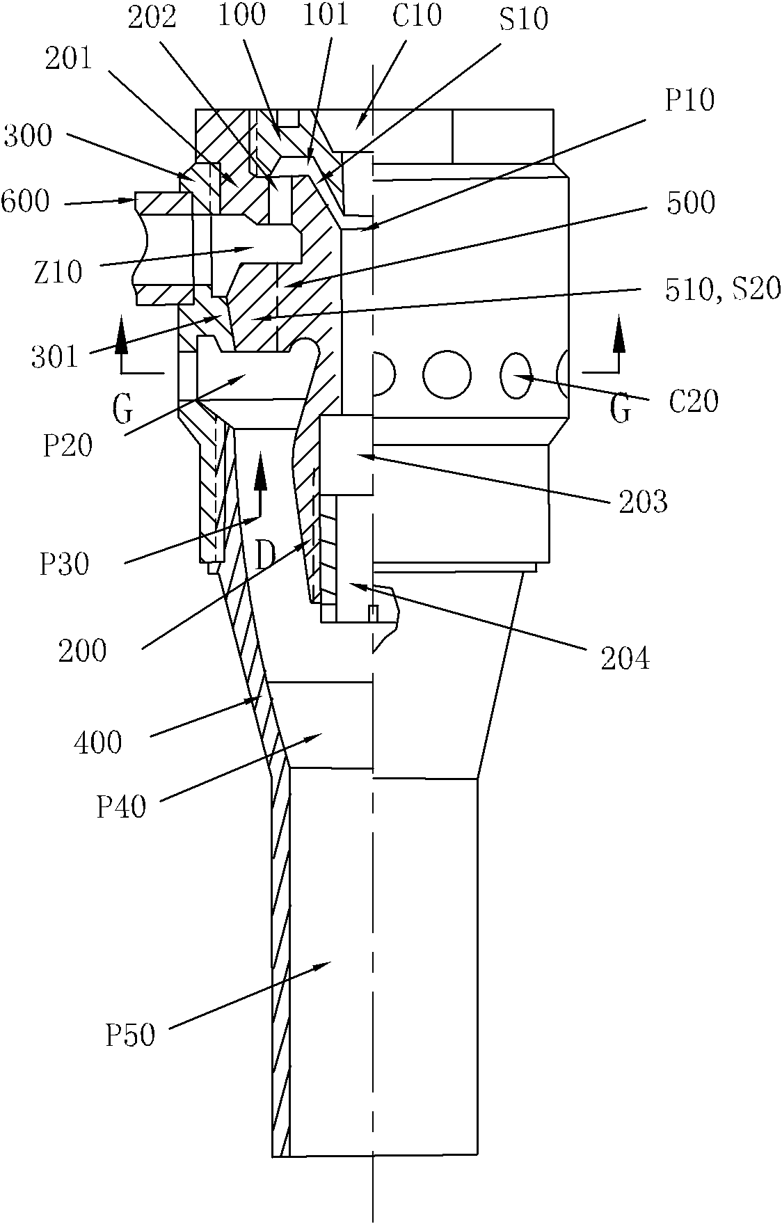
[0056] For a second embodiment of the double-ring injector of the present invention, see image 3 . In this embodiment, the inner ring injector assembly is coaxially sleeved in the outer ring injector assembly.

[0057] The inner ring injector assembly is coaxially provided with a central secondary fluid inlet sleeve 100 and an inner tube 200 along the central axis. The inlet C10 caliber of the central secondary fluid inlet sleeve 100 is larger than the outlet caliber. The front end of the inner pipe 200 is provided with a cup-shaped flared wall 201, and the inner wall of the cup-shaped flared wall 201 is in sealing connection with the outer wall of the central secondary fluid inlet sleeve 100. The sealed connection can be as follows: image 3 Threaded or flanged connections shown. An annular flat cavity 101 is formed between the concave middle end surface of the cup-shaped flared wall 201 at the front end of the inner tube 200 and the concave bottom groove of the central s...

Embodiment 3

[0066] The third embodiment of the double ring injector of the present invention, see Figure 7 , In this embodiment, the inner ring injector assembly is coaxially sleeved in the outer ring injector assembly. The outer ring injector assembly sets the total mixing output pipe rearwardly along the central axis.

[0067] The inner ring injector assembly is coaxially provided with a central secondary fluid inlet sleeve 100' and an inner tube 200' along the central axis. The diameter of the inlet C10' of the central secondary fluid inlet sleeve 100' is greater than the diameter of the outlet. The bottom surface of the circular platform at the rear end of the central secondary fluid inlet sleeve 100' is provided with a plurality of inclined grooves 102' evenly distributed on the outer wall 101' of the tapered ring sleeve protruding rearward (also can be straight grooves or dense patterns), see Figure 8 . These chutes 102' do not intersect the centerline of the central secondary ...


PUM


Abstract

The invention provides to a dual ring ejector, and relates to a fluid pump. An inner ring ejector apparatus is sequentially provided with a central time fluid inlet sleeve, an inner ring nozzle and a center mixing tube along an axle wire, a main stream annular cavity, an outer ring nozzle, an annular mixing room and an annular mixing tube are sequentially arranged on the periphery of the inner ring ejector apparatus along the axle wire by an outer ring ejector apparatus, a main stream inlet tube is communicated with an inner ring nozzle inlet and an outer ring nozzle inlet through the main stream annular cavity, the annular mixing room is communicated with an outer ring stream inlet tube and the annular mixing tube, an outer ring nozzle outlet is convex and protrudes into the annular mixing room and faces to the annular mixing tube, the two outlets of the mixing tubes are jointly communicated with a general mixing output tube, the same main stream is used by the inner ring ejector and the outer ring ejector for pumping time fluid, and after being mixed, the pumped time fluid enters the general mixing output tube for outputting. According to the dual ring ejector, the weight is light, the size in axial direction is small, the absorbing and ejecting rate is high, and the ejector performs well with mass flow and has various structure forms. The main stream can be used for injecting and mixing one or two time fluids, so as to realize output under uniform pressure.

Description

technical field [0001] The invention belongs to a fluid pump, and relates to an injector for mixed fluid, in particular to a double-ring injector for mixed fluid injection. Background technique [0002] Ejector, also called jet pump, is a device that injects low pressure (or no pressure) secondary fluid with relatively high pressure primary fluid, and completes primary fluid suction secondary fluid for mixed flow delivery. Since the injector has no moving parts, it is reliable and widely used in fluid equipment in various fields. [0003] Existing injector is made up of main fluid inlet pipe, main fluid nozzle, secondary fluid inlet, mixing chamber, mixing pipe or mixing diffuser; The ejected main fluid jet is sucked into the mixing tube, mixed and equalized in the mixing diffuser and output. The mixing tube of such injectors is generally a single elongated circular tube, such as a typical Venturi tube. [0004] British Patent Application Publication No. WO2006 / 010949 dis...

Claims


Application Information

Patent Timeline
IPC IPC(8): F04F5/00
Inventor 韩铁夫
Owner 韩铁夫
Why Eureka
Try Eureka