

Electronic Hydraulic Brake Device
A hydraulic brake and electronic technology, applied in the direction of hydraulic brake transmission, brake transmission, brakes, etc., to achieve the effect of improving assembly, reducing weight, and alleviating the difference in pedal feel
- Summary
- Abstract
- Description
- Claims
- Application Information
AI Technical Summary
Problems solved by technology
Method used
Image

Examples
Embodiment Construction
[0041] Embodiments of the electronic hydraulic brake device according to the present invention will be described below with reference to the accompanying drawings. In the process, the thickness of lines or the size of structural elements, etc. shown in the drawings may be shown enlarged for clarity and convenience in description. In addition, terms described later are terms defined in consideration of functions in the present invention, and may be different according to user's or operator's intention or custom. Therefore, the definition for this term should be determined based on the contents of the entire specification.
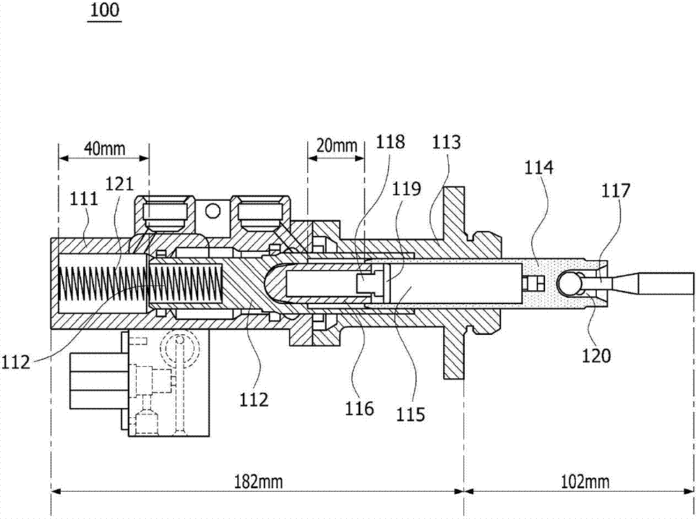
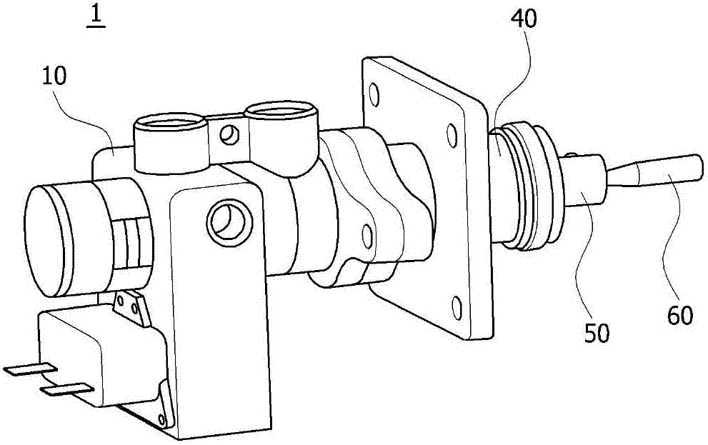
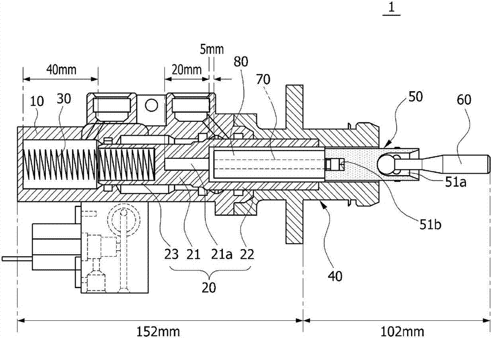
[0042] figure 2 is a perspective view schematically showing an electronic hydraulic brake device according to the present invention, image 3 is a sectional view schematically showing an electronic hydraulic brake device according to the present invention, Figure 4 is a diagram schematically showing the main piston part in the electronic hydraulic brake...
PUM
 Abstract
Description
Claims
Application Information