

Principal axis device
A main shaft device and main shaft technology, applied in the directions of shafts, bearings, liquid cushion bearings, etc., can solve the problems of unstable main shaft and reduced bearing rigidity, and achieve the effect of improving operating capacity, increasing natural frequency, and simplifying air bearing structure.
- Summary
- Abstract
- Description
- Claims
- Application Information
AI Technical Summary
Problems solved by technology
Method used
Image

Examples
no. 1 Embodiment approach
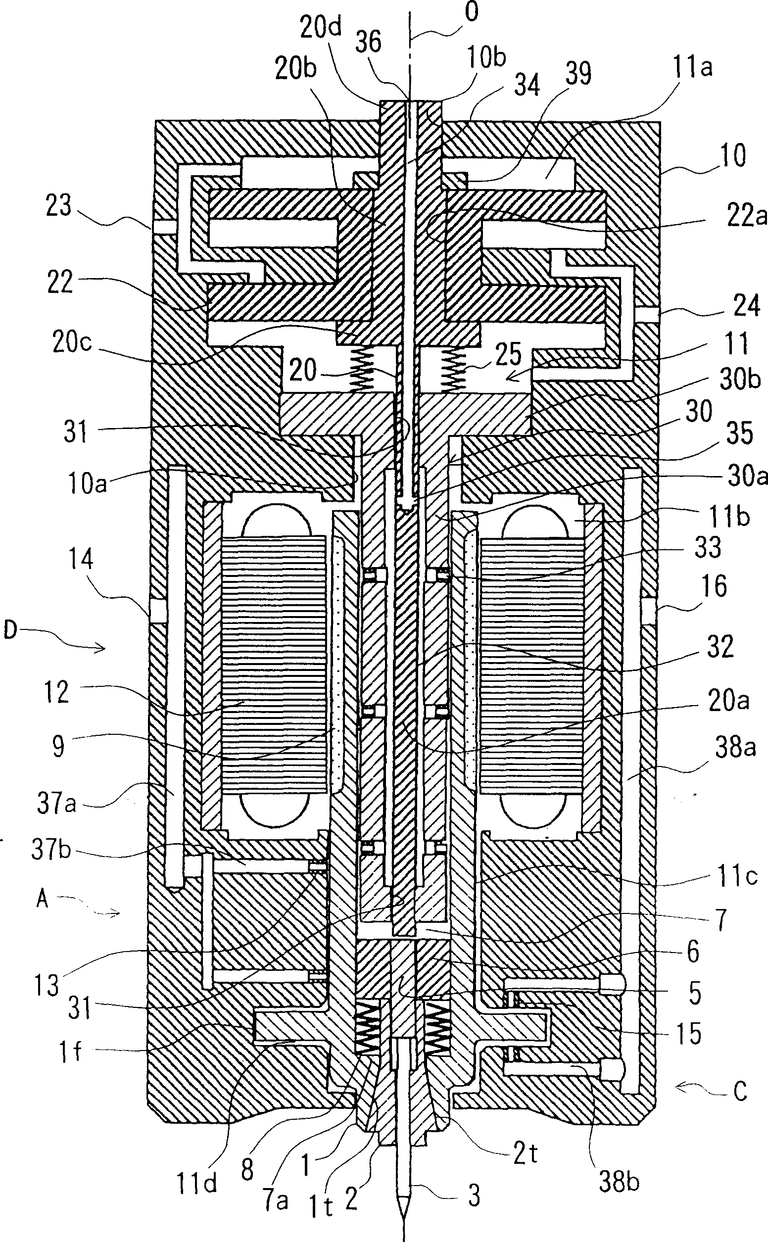
[0033] figure 1 is a cross-sectional view of the spindle device according to the first embodiment of the present invention, having the same Figure 5 Elements of the same configuration, elements (components) having the same function, and elements (components) having the same function although slightly different in shape are given the same reference numerals and their descriptions are omitted.
[0034] The spindle device in this embodiment has one end ( figure 1 The main shaft 1 having a slotted collet (tool holding mechanism) 2 and a gas bearing mechanism capable of supporting the main shaft 1 rotatably on a housing (casing member) 10 are provided.
[0035] Housing 10 has along the axial direction ( figure 1 up and down direction) hole 11. The hole 11 includes two chambers 11a for accommodating the two pistons 22, a coil accommodating portion 11b for accommodating the coil 12, a shaft accommodating portion 11c for accommodating the front end portion of the main shaft 1 rota...
no. 2 Embodiment approach
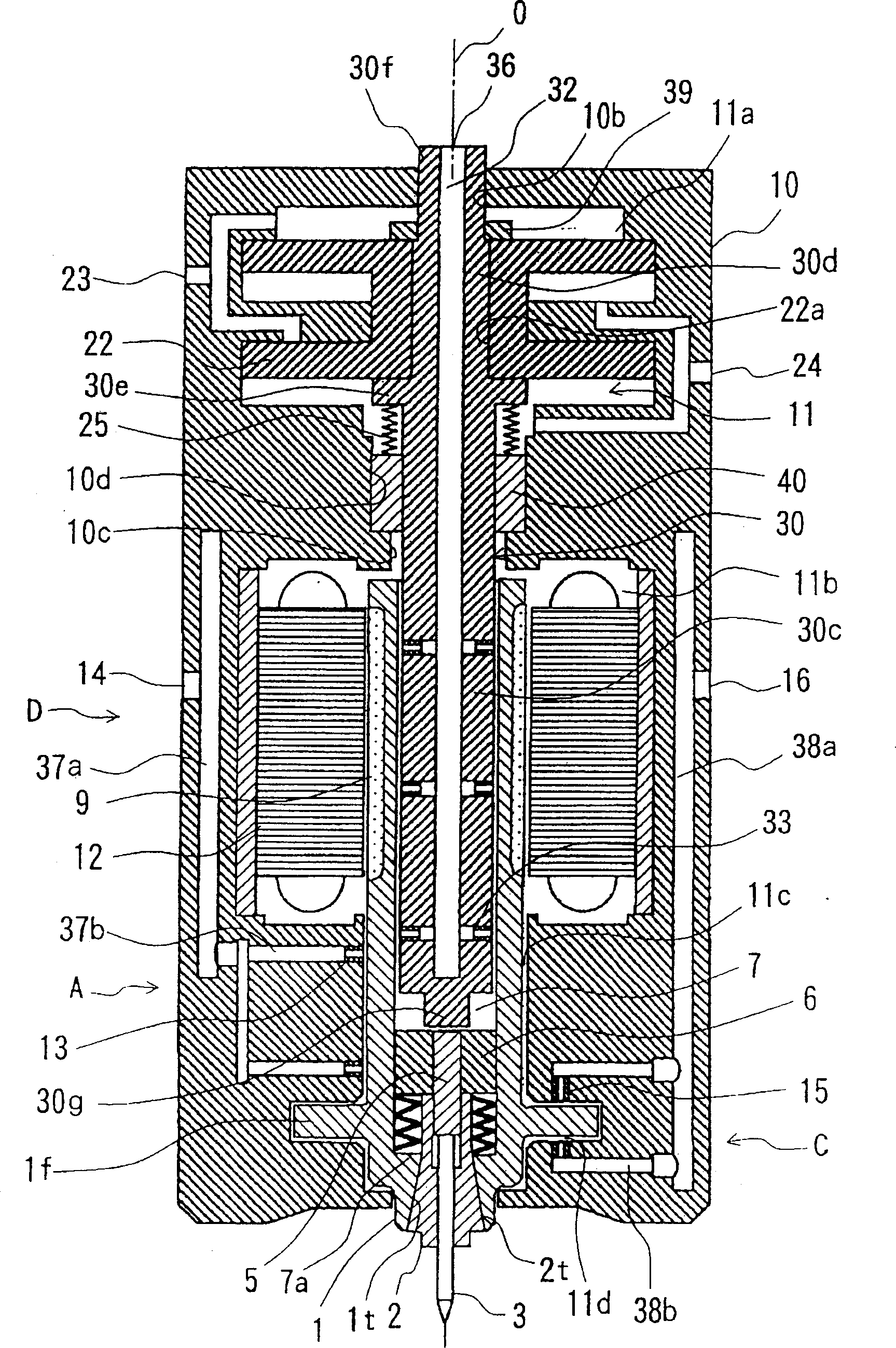
[0049] Next, press figure 2 A second embodiment according to the present invention will be described. The figure is a sectional view of the spindle device according to the present embodiment. Due to this implementation, with figure 1 Compared with the previous embodiment shown in , only the central guide rod 30 is integrally formed with the push rod 20, and the other parts are substantially the same, so the figure 1 , Figure 5 Elements of the same configuration, elements (components) having the same function, and elements (components) having the same function although slightly different in shape are given the same reference numerals and their descriptions are omitted.
[0050] That is, a small diameter portion 10d is provided between the cavity 11a at the inner side of the housing 10 and the coil accommodating portion 11b, and is fixed in a state of engaging with the cylindrical guide member 40, and the small diameter portion 10d The stepped portion 10c formed on the lo...
no. 3 Embodiment approach
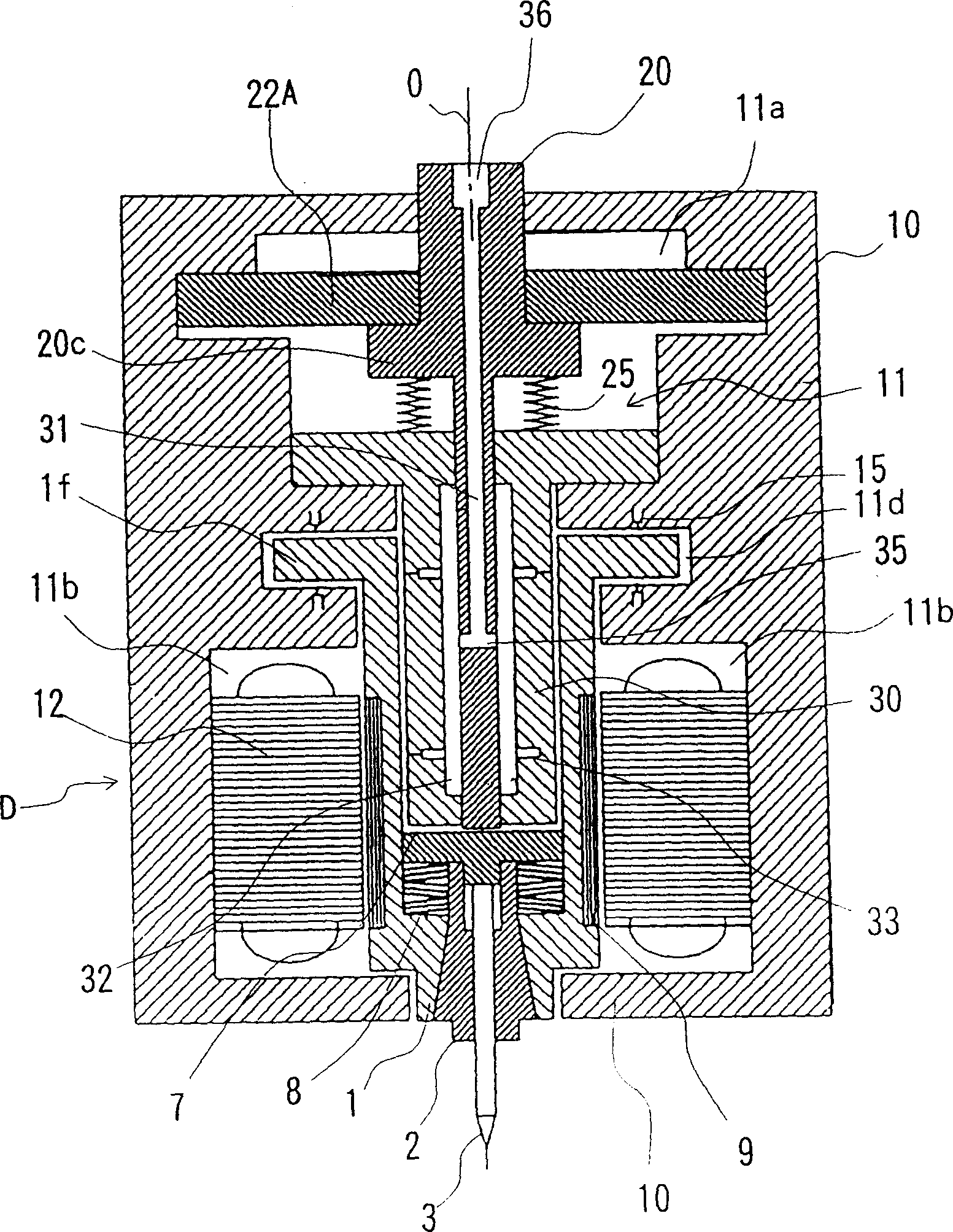
[0056] image 3 is a cross-sectional view of a spindle device according to a third embodiment of the present invention, having the same figure 1 ,Figure 5 Elements of the same configuration, elements (components) having the same function, and elements (components) having the same function although slightly different in shape are given the same reference numerals and their descriptions are omitted.
[0057] The main shaft device in this embodiment, and figure 1 The spindle unit shown in is different in that the air bearing A is not provided, and on the opposite side of the slotted collet (tool holder) 2 at the front end of the spindle 1 ( image 3 The point of disposing the flange 1f, and the point of making the piston 22A that constitutes the piston 22 by one (one series). With this, figure 1 An air supply hole (gas ejection hole) 15 provided centrally below is provided at a central portion of the housing 10 at a portion facing the flange 1f.
[0058] Where the bearing ...
PUM
 Abstract
Description
Claims
Application Information