Broadband beam scanning reflective array antenna

A reflectarray antenna and beam scanning technology, which is applied in antennas, resonant antennas, electrical short antennas, etc., can solve the problems of narrow bandwidth and low aperture efficiency

Inactive Publication Date: 2021-07-13
XIDIAN UNIV
View PDF14 Cites 5 Cited by
  • Summary
  • Abstract
  • Description
  • Claims
  • Application Information

AI Technical Summary

Problems solved by technology

[0006] The purpose of the present invention is to overcome the defects in the above-mentioned prior art, and propose a broadband beam scanning reflectarray antenna, which is used to solve the technical problems of narrow bandwidth and low aperture efficiency in the prior art

Method used


Image

  • Broadband beam scanning reflective array antenna
  • Broadband beam scanning reflective array antenna
  • Broadband beam scanning reflective array antenna

Examples


Embodiment Construction

[0027] Below in conjunction with accompanying drawing and specific embodiment, the present invention is described in further detail:

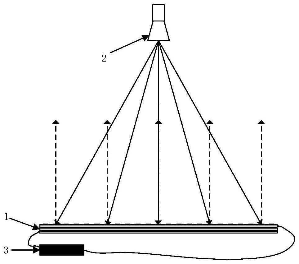
[0028] refer to figure 1 , the present invention includes a reflective array 1, a feed source 2 and a main control circuit board 3 fixed at its focal position.

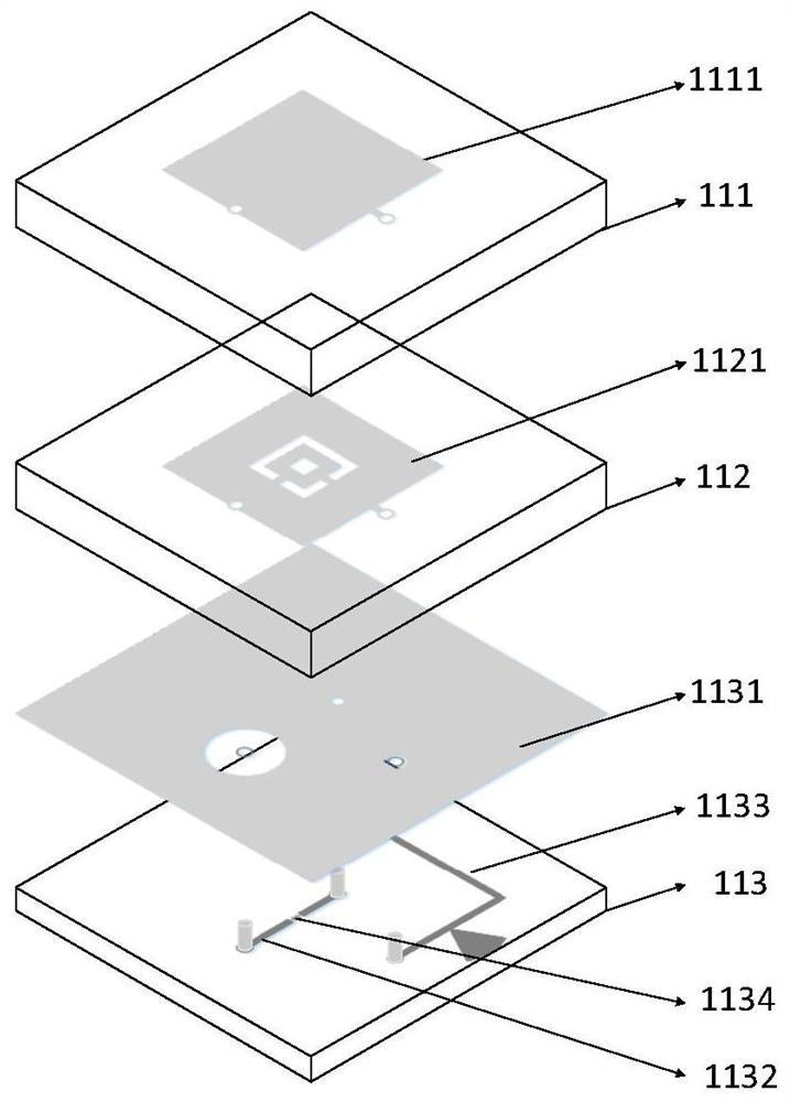
[0029] The reflective array 1 adopts a square array with a side length of 190 mm, including M×N periodically arranged reconfigurable reflective array units 11, M≥2, N≥2, and M=N=20 in this embodiment; The reconfigurable reflectarray unit 11 has a structure such as figure 2 As shown, it includes a first dielectric substrate 111, a second dielectric substrate 112, and a third dielectric substrate 113 that are stacked sequentially from top to bottom and have the same thickness; A square with a side length equal to 9.5mm has a thickness of 1mm, 1mm, and 0.5mm. By stacking the first dielectric substrate 111 and the second dielectric substrate together, the problem of increased loss of t...


PUM


Abstract

The invention provides a broadband beam scanning reflective array antenna, which is used for solving the technical problems of narrower bandwidth and low aperture efficiency in the prior art, and comprises a reflective array consisting of M * N reconfigurable reflective array units which are periodically arranged, a feed source fixed at the focus position of the reflective array, and a main control circuit board, the reconfigurable reflective array unit comprises a first dielectric substrate, a second dielectric substrate and a third dielectric substrate, wherein the first dielectric substrate and the second dielectric substrate are sequentially stacked from top to bottom and are equal in thickness. The square radiation patch is printed on the upper surface of the first dielectric substrate; the upper surface of the second dielectric substrate is printed with a double-side annular radiation patch; the upper surface of the third dielectric substrate is printed with a reflection floor etched with a choke ring, the lower surface of the third dielectric substrate is printed with a first rectangular microstrip line and a direct current bias line, and the first rectangular microstrip line is etched with a rectangular gap dividing the first rectangular microstrip line into two parts for loading a PIN diode; and the square radiation patch and the double-side annular radiation patch are connected in parallel through a first metalized via hole and then are connected in series with a PIN diode and a direct current bias line.

Description

technical field [0001] The invention belongs to the technical field of antennas, and relates to a reflection array antenna, in particular to a broadband beam scanning reflection array antenna, which can be used in the fields of deep space detection, microwave remote control, radar imaging, long-distance wireless communication and the like. Background technique [0002] A reflectarray antenna is composed of a space feed and a periodically arranged reflectarray. Its working mechanism is: the space feed emits electromagnetic waves, which reach the reflection array surface through different paths, and the units located at different aperture positions have different spatial phase delays, and each reflection unit has the function of compensating the phase, passing through the reflection array surface After reflection, the required high-gain radiation characteristics are finally formed; however, in order to meet the requirements of modern communication systems for antenna functiona...

Claims


Application Information

Patent Timeline
IPC IPC(8): H01Q9/04H01Q1/00H01Q3/34H01Q15/14H01Q23/00
CPCH01Q9/0414H01Q9/0464H01Q1/002H01Q3/34H01Q15/14H01Q23/00
Inventor 赵钢周世国陈官韬罗传威焦永昌徐贺姜旭鸿李威宗
Owner XIDIAN UNIV
Why Eureka
Try Eureka