
Electric appliance cabinet capable of preventing hot-line work

A technology for live work and electrical cabinets, applied in electrical equipment shells/cabinets/drawers, electrical components, cabinets/boxes/drawer parts, etc. , the effect of device function recovery

Active Publication Date: 2021-07-16
STATE GRID HEILONGJIANG ELECTRIC POWER COMPANY +1
View PDF7 Cites 3 Cited by
  • Summary
  • Abstract
  • Description
  • Claims
  • Application Information

AI Technical Summary

Problems solved by technology

[0005] The object of the present invention is to provide an electrical cabinet that prevents live work to solve the above-mentioned background technology. The electrical cabinets currently on the market are all opened with a key or can be opened directly. The wiring inside the cabinet should be inspected and repaired. If the operator makes mistakes and the electrical cabinet is not completely powered off, it may cause the danger of electric shock to the operator.

Method used


Image

  • Electric appliance cabinet capable of preventing hot-line work
  • Electric appliance cabinet capable of preventing hot-line work
  • Electric appliance cabinet capable of preventing hot-line work

Examples


Embodiment 1

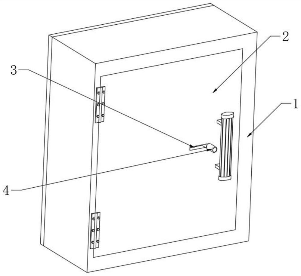
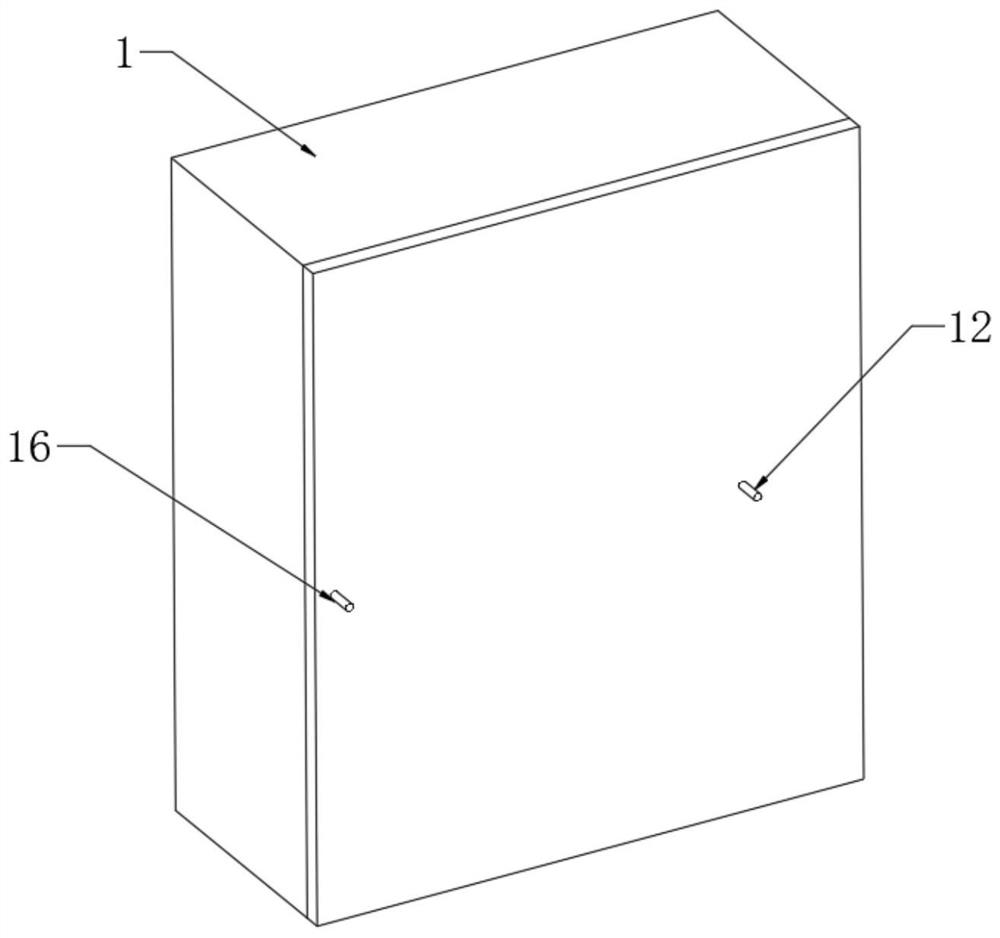
[0023] refer to Figure 1-5 , an electrical cabinet for preventing live work, including a cabinet body 1 and electrical components 11, the front of the cabinet body 1 is hinged to a cabinet door 2, and the inner wall of the cabinet door 2 is fixedly provided with a locking member 10, and the electrical components 11 are installed on Inside the cabinet 1, the electrical components 11 are provided with a positive lead 12 and a negative lead 13, the positive lead 12 runs through the rear side wall of the cabinet 1 and is connected to the mains, and the other end of the negative lead 13 is fixedly connected to a conductive spring 19, The inner rear side wall of the cabinet body 1 is provided with a chute 14, and an iron slider 17 is slidably connected to the chute 14, and one side wall of the iron slider 17 is fixedly connected with an iron clip 18, and The clip 18 is fixedly connected with the other end of the conductive spring 19. The outer side of the conductive spring 19 is co...

Embodiment 2

[0027] refer to Figure 4-5 The difference between this embodiment and Embodiment 1 is that an iron core 20 is fixedly connected to the inner wall of the cabinet body 1, and the iron core 20 is located inside the conductive spring 19, and one end of the iron core 20 close to the iron slider 17 is fixedly connected with a Rubber pad22.

[0028] In long-term use, if the conductive spring 19 is damaged, the conductive spring 19 will stretch under the energized state. At this time, the iron core 20 and the conductive spring 19 form an electromagnet, which attracts the iron slider 17 by magnetic force, so that the iron slider 17 Offset with the rubber pad 22, even if the conductive spring 19 is damaged, the cabinet door 2 can only be opened when the electrical element 11 is powered off, increasing the fault tolerance of the equipment.

Embodiment 3

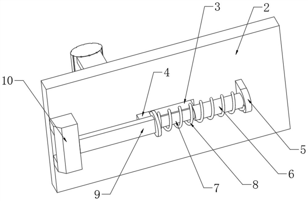
[0030] refer to image 3 The difference between this embodiment and Embodiment 1 is that: the side wall of the cabinet door 2 is provided with a through hole 3, the inner wall of the cabinet door 2 is fixedly connected with a fixed block 5, and one side wall of the fixed block 5 is fixedly connected with a sleeve The other end of the pipe 6 and the casing 6 is slidably inserted with a sliding rod 7, the other end of the sliding rod 7 is fixedly connected with a connecting rod 9, and the other end of the connecting rod 9 is fixedly connected with a locking member 10, and the outer sleeve of the casing 6 A return spring 8 is provided, and the two ends of the return spring 8 are respectively fixedly connected with the fixed block 5 and the connecting rod 9, and the side wall of the connecting rod 9 close to the through hole 3 is fixedly connected with the moving block 4, and the moving block 4 runs through the through hole 3 .

[0031] Under special conditions, if live maintenan...


PUM


Abstract

The invention discloses an electric appliance cabinet capable of preventing hot-line work. The cabinet comprises a cabinet body and an electric appliance element, a cabinet door is connected to the front of the cabinet body through a hinge, a locking piece is fixedly arranged on the inner wall of the cabinet door, the electric appliance element is arranged in the cabinet body, and a positive wire and a negative wire are arranged on the electric appliance element. The positive wire penetrates through the rear side wall of the cabinet body and is connected with a mains supply, the other end of the negative wire is fixedly connected with a conductive spring, a sliding groove is formed in the rear side wall of the interior of the cabinet body, an iron sliding block is slidably connected into the sliding groove, and an iron clamping piece is fixedly connected to the side wall of one side of the iron sliding block; and the iron clamping piece is fixedly connected with the other end of the conductive spring. The invention relates to the technical field of electric appliance cabinets. The principle that the spring can contract when conducting electricity is utilized to control the locking state of the cabinet door, so that when an electric appliance element circuit is not broken, the cabinet door cannot be opened, and dangers caused by live-line work due to the fact that an operator does not power off in time are prevented.

Description

technical field [0001] The invention relates to the technical field of electrical cabinets, in particular to an electrical cabinet for preventing electrified work. Background technique [0002] The electrical cabinet is a cabinet for centralized installation of electrical components, which can protect the electrical components installed in it, and make the arrangement of electrical components more reasonable, shorten the distance of circuit connections, and can centrally dissipate heat. [0003] At present, the electrical cabinets on the market are opened with a key or can be opened directly. After the operator opens the electrical cabinet, he can repair the wiring inside the electrical cabinet. If the operator makes a mistake and the electrical cabinet is not completely powered off, then There may be a risk of electric shock to the operator. [0004] For this reason, we propose an electrical cabinet to prevent live work to solve the above problems. Contents of the invent...

Claims


Application Information

Patent Timeline
Patent Type & Authority Applications(China)
IPC IPC(8): H05K5/02
CPCH05K5/0217H05K5/0247H05K5/0208
Inventor 孙超韩
Owner STATE GRID HEILONGJIANG ELECTRIC POWER COMPANY
Learn More