
Electric wire anti-bird-nesting mechanism based on pressure bar structure

一种电线、压杆的技术,应用在电线防鸟筑巢机构领域,能够解决危险系数高、人工清除难度大等问题,达到结构可靠、防止鸟类筑巢、强实用性的效果

Active Publication Date: 2017-10-03
MINGGUANG JIUZHI INTELLECTUAL PROPERTY MANAGEMENT CO LTD
View PDF8 Cites 2 Cited by
  • Summary
  • Abstract
  • Description
  • Claims
  • Application Information

AI Technical Summary

Problems solved by technology

However, because birds nesting on the wires will affect the current on the high-voltage circuit, especially on some power transmission lines that require a relatively high level of safety, special attention must be paid to prevent bird damage and ensure the safety of the power grid. , manual removal is difficult, wide-ranging, and has a high risk factor. Therefore, a mechanism that can automatically clean wires and debris to prevent birds from nesting is very much needed. Utilizing the clean energy that is ubiquitous in nature, on the one hand, it can clean the wires and bird nests at any time. Nest debris prevents birds from building nests. On the other hand, it can also drive birds to stay on the wires, fundamentally solving bird problems.

Method used


Image

  • Electric wire anti-bird-nesting mechanism based on pressure bar structure
  • Electric wire anti-bird-nesting mechanism based on pressure bar structure
  • Electric wire anti-bird-nesting mechanism based on pressure bar structure

Examples


Embodiment Construction

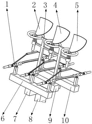
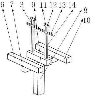
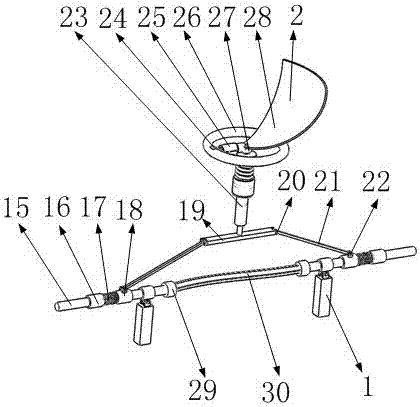
[0029] Such as figure 1 , 3 , 4, it includes the power line support 1, the first power line 2, the second power line 4, the third power line 5, the first support beam 6, the cross beam 7, the pillar 8, the second support beam 9, the third The support beam 10, the first support frame 3, the second support frame 11, and the wires 15, wherein the cross beam 7 is installed at the upper end of the pillar 8, and the first support beam 6, which is perpendicular to it, is installed on the top of the cross beam 7 from one end to the other end. The second support beam 9 and the third support beam 10, the cross beam 7 is used to support the first support beam 6, the second support beam 9 and the third support beam 10, the first support beam 6 and the third support beam 10 each have three A power line support 1 is installed equidistantly, and the first power line 2, the second power line 4 and the 3 groups of the power line supports 1 corresponding to the first support beam 6 and the third ...


PUM


Abstract

The invention belongs to the field of high-voltage electricity safety technology, and particularly relates to an electric wire anti-bird-nesting mechanism based on a pressure bar structure. The electric wire anti-bird-nesting mechanism comprises a wind pendulum, a spherical hinge, a telescopic rod, an oil cylinder, a cross bar, an inclined supporting rod, an articulated sliding sleeve, an inertial spring, an inertial sliding sleeve and an electric wire, wherein the power of the mechanism is sourced from the natural wind energy, when the wind acts on the wind pendulum, the wind energy is converted to mechanical energy, the telescopic rod and the spherical hinge ensure that the wind pendulum performs rotation and downward swinging motion without interference, the hydraulic oil in the oil cylinder is compressed, the mechanical energy is converted to pressure energy, and thus the cross bar that is connected with the oil cylinder moves, the liquid pressure energy is converted to the mechanical energy again during the period, and then the power is delivered to the inertial sliding sleeve from the cross bar, the inclined supporting rod, the articulated sliding sleeve and the inertial spring to ensure that the inertial sliding sleeve can perform reciprocating sliding on the electric wire to knock off sundries that are used for birds to nest on the electric wire. According to the electric wire anti-bird-nesting mechanism disclosed by the invention, under the action of the natural clean energy-wind energy, the mechanism can continuously play the role and also is reliable in structure and relatively strong in practicability.

Description

[0001] This application is a divisional application of the invention patent application titled: Wire Bird Nesting Mechanism Based on Pressure Rod Structure, Application Date: August 20, 2016, Application Number: 201610690914.4. Technical field [0002] The invention belongs to the technical field of high-voltage electrical safety, and in particular relates to a wire anti-bird nesting mechanism based on a pressure rod structure. Background technique [0003] With the development of the power industry, high-voltage wires are widely used in the process of long-distance power transmission due to their low energy consumption. However, because birds staying and building nests on wires will have an impact on the current on high-voltage circuits, especially on transmission lines with relatively high safety levels, special attention should be paid to preventing bird damage and ensuring the safety of the power grid. , Manual removal is difficult, wide-ranging, and high-risk. Therefore, ther...

Claims


Application Information

Patent Timeline
Patent Type & Authority Applications(China)
IPC IPC(8): H02G7/00A01M29/32
CPCA01M29/00A01M29/06A01M29/32H02G7/00
Inventor 沈宇杰
Owner MINGGUANG JIUZHI INTELLECTUAL PROPERTY MANAGEMENT CO LTD
Learn More