Hand pressing type atomizing pump

A spray pump and hand pressure technology, applied in the field of spray parts, can solve the problems of insufficient pressure, strong spray force, and inability to atomize the liquid, and achieve the effects of simple structure, moderate spray force, and convenient installation.

Pending Publication Date: 2021-07-20
施云鹏
View PDF0 Cites 0 Cited by
  • Summary
  • Abstract
  • Description
  • Claims
  • Application Information

AI Technical Summary

Problems solved by technology

[0002] Spray is used in cosmetics and other fields. The spray pump is one of the key components. After the traditional spray pump is pressed, the liquid in the pump body is sprayed out. During the spraying process, the pressure in the pump body gradually decreases. Insufficient pressure causes the liquid to not be atomized, resulting in dripping. In addition, the traditional spray pump uses a spring as a booster, and the spray force is too strong.

Method used


Image

  • Hand pressing type atomizing pump
  • Hand pressing type atomizing pump
  • Hand pressing type atomizing pump

Examples


Embodiment

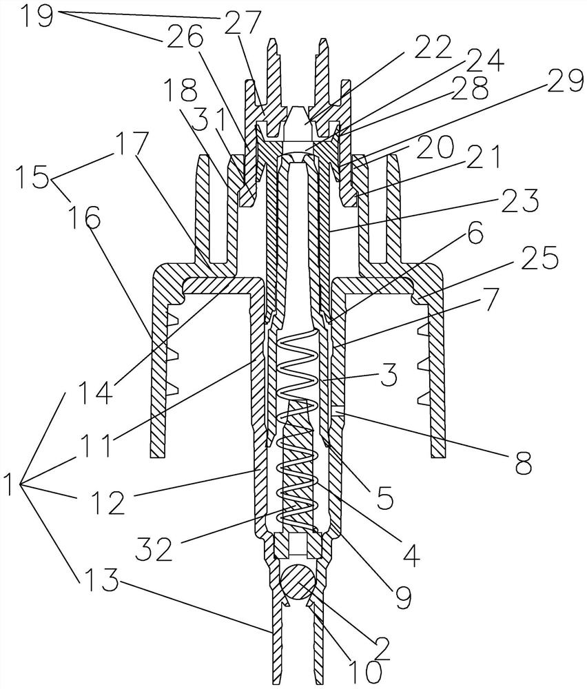
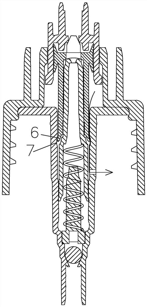
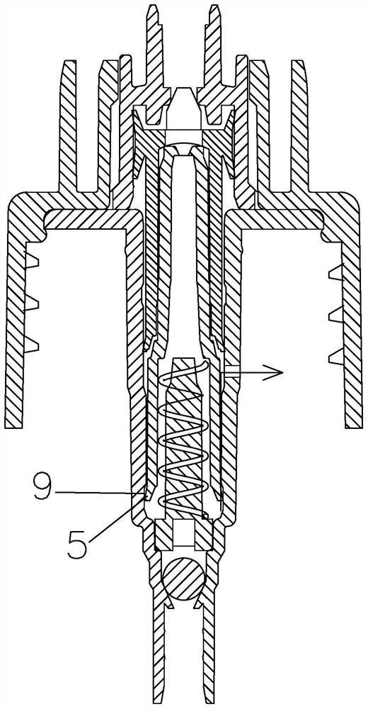
[0021] see Figure 1 to Figure 3 , a hand-operated spray pump, comprising a pump body 1, a sealing ring 10 located at the bottom of the pump body 1, a sealing ball 2 located at the bottom of the pump body 1, the sealing ball 2 is located on the upper side of the sealing ring 10, and an insertion The lower piston 3 on the upper end of the pump body 1, the upper piston 23 sleeved on the upper end of the lower piston 3, the spring 4 located in the pump body 1 for driving the lower piston 3 to move away from the pump body 1, the inner wall of the upper piston 23 is located On one conical surface, the outer wall of the lower piston 3 is located on the other conical surface, and the lower piston 3 is in interference fit with the upper piston 23; the lower piston 3 is provided with a spring seat 32, and the lower end of the spring seat 32 is connected to the suction The upper end of the liquid section 13, the upper end of the spring 4 abuts against the lower piston 3, the spring 4 is...


PUM


Abstract

The invention discloses a hand pressing type atomizing pump, and relates to the technical field of atomizing parts. The hand pressing type atomizing pump comprises a pump body, a sealing ring located at the bottom end of the pump body and a sealing ball located at the bottom end of the pump body. The sealing ball is located on the upper side of the sealing ring. The hand pressing type atomizing pump further comprises a lower piston inserted to the upper end of the pump body, an upper piston sleeving the upper end of the lower piston and a spring located in the pump and used for driving the lower piston to move to the direction away from the pump body. A via hole is formed in the upper end of the upper piston, the lower end of the lower piston is a lower sealing part attached to the inner wall of the pump body, the lower end of the upper piston is an upper sealing part attached to the inner wall of the pump body, an annular ventilation groove is formed in the position, between the upper sealing part and the lower sealing part, of the inner wall of the pump body, a hole is formed in the position, between the ventilation groove and the lower sealing part, of the pump body, and an annular liquid-permeable groove is formed in the position, between the lower sealing part and the sealing ball, of the pump body. The hand pressing type atomizing pump is free of water dripping and moderate in spraying force.

Description

technical field [0001] The invention belongs to the technical field of spray parts, in particular to a hand-pressed spray pump. Background technique [0002] Spray is used in cosmetics and other fields. The spray pump is one of the key components. After the traditional spray pump is pressed, the liquid in the pump body is sprayed out. During the spraying process, the pressure in the pump body gradually decreases. Insufficient pressure causes the liquid to not be atomized, resulting in dripping. In addition, the traditional spray pump uses a spring as a booster, and the spray force is too strong. Contents of the invention [0003] The purpose of the present invention is to overcome the shortcomings of dripping phenomenon and too strong spraying force in the prior art, and propose a hand-pressed spray pump with no dripping phenomenon and moderate spraying force. [0004] In order to achieve the above object, the present invention adopts the following technical solutions: ...

Claims


Application Information

Patent Timeline
Patent Type & Authority Applications(China)
IPC IPC(8): B65D47/34
CPCB05B11/1043B05B11/1042B05B11/1001
Inventor 施云鹏
Owner 施云鹏
Why Eureka
Try Eureka