Method and device for measuring, predicting and optimizing milling tool marks on top surface of engine cylinder block

A technology of engine block and optimization method, which is applied in the direction of measuring/indicating equipment, milling machine equipment, milling machine equipment details, etc., to achieve the effect of strong theoretical persuasion and strong prediction accuracy

Active Publication Date: 2021-07-23
力度工业智能科技(苏州)有限公司
View PDF7 Cites 2 Cited by
  • Summary
  • Abstract
  • Description
  • Claims
  • Application Information

AI Technical Summary

Problems solved by technology

This method provides a visual reference for controlling and reducing the waviness of the milling surface of the part. However, this method still ignores the mechanism of waviness error, and does not consider the actual factors such as spindle tilt, tool wear and tool jump from the perspective of physical nature. Therefore, this method has certain limitations for the prediction of waviness error and the optimization of milling process parameters.

Method used


Image

  • Method and device for measuring, predicting and optimizing milling tool marks on top surface of engine cylinder block
  • Method and device for measuring, predicting and optimizing milling tool marks on top surface of engine cylinder block
  • Method and device for measuring, predicting and optimizing milling tool marks on top surface of engine cylinder block

Examples


Embodiment 1

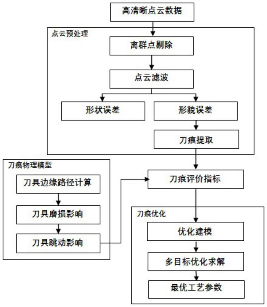
[0038] Such as Figure 1 to Figure 7 As shown, in this embodiment, the measurement prediction and optimization method based on the milling tool marks on the top surface of the engine block provided by the present invention includes the following steps:

[0039] Step 1: Preprocess the original 3D point cloud data of the top surface of the engine block obtained by high-definition measurement methods, including three operations of outlier elimination, filtering and knife mark conversion. For a known type of cylinder workpiece, the nominal height from the measurement plane to the reference plane is a known definite value, and the deviation between the measured actual height and the nominal height can also be obtained by subtracting the two. The critical threshold P is preset, and if the deviation value of any data point is greater than P, the data point will be regarded as an outlier and eliminated. After the outlier is eliminated, the point cloud data is filtered using the jigsa...


PUM


Abstract

The invention discloses a method and device for measuring, predicting and optimizing milling tool marks on the top surface of an engine cylinder block. The method comprises the steps that preprocessing of cylinder block top surface point cloud data obtained through high-definition measurement is conducted, abnormal outliers are removed, filtering of the point cloud data is conducted, the tool mark features in a high-pass signal are extracted, and a three-dimensional evaluation index of the tool marks is defined; according to the milling machining characteristics of the top face of the engine cylinder block, influences caused by spindle inclination, tool abrasion and tool jumping are comprehensively considered, and physical modeling is conducted on the tool mark forming process; and the milling surface quality is predicated according to a tool mark physical model, a three-dimensional evaluation index numerical value of the tool marks generated under a specific process parameter condition is calculated, a process parameter multi-target optimization model is established on the basis, and an optimization model is solved to obtain an optimal process parameter scheme suitable for milling the top surface of the engine cylinder block. According to the method, milling surface tool mark feature indexes are defined and accurately predicted, so that the milling process parameters of the top surface of the engine cylinder block are effectively optimized, and the milling quality of the top surface of the engine cylinder block is improved.

Description

technical field [0001] The invention relates to surface processing of an engine cylinder block, in particular to a method for measuring, predicting and optimizing tool marks based on engine cylinder top surface milling. Background technique [0002] The engine block is one of the core components of the engine. The machining accuracy of its key surfaces will directly affect the service performance of the automobile engine. Among them, the top surface of the engine block is the joint surface with the engine cylinder head, and its milling quality will directly affect Engine tightness. In the milling process of the top surface of the engine block, due to the influence of factors such as spindle tilt, tool wear and tool jump, there will often be tool mark morphology errors between the macroscopic flatness error and the microscopic roughness error. The surface features will directly affect the waviness error of the processing plane, and then determine the sealing performance of t...

Claims


Application Information

Patent Timeline
Patent Type & Authority Applications(China)
IPC IPC(8): B23C3/00B23Q17/20G05B19/19
CPCB23C3/00B23Q17/20G05B19/19
Inventor 杜世昌李贵龙
Owner 力度工业智能科技(苏州)有限公司
Why Eureka
Try Eureka