
Permanent magnet coupler test bed control system

A permanent magnet coupling and control system technology, which is applied in the testing of machine/structural components, instruments, and mechanical components, etc. Inconvenient adjustment of the angle between the frame and the right frame, etc., to achieve the effect of improving practicability

Pending Publication Date: 2021-07-23
嘉兴美茵钛传动科技有限公司
View PDF1 Cites 0 Cited by
  • Summary
  • Abstract
  • Description
  • Claims
  • Application Information

AI Technical Summary

Problems solved by technology

[0003] The Chinese patent application number is CN102323065 A discloses a coupling test method and a test bench, the equipment is inconvenient to adjust the angle of the left bench and the right bench, and it cannot be observed at the first time when the shaft coupling is tested Coupling rotation angle, less practical

Method used


Image

  • Permanent magnet coupler test bed control system
  • Permanent magnet coupler test bed control system
  • Permanent magnet coupler test bed control system

Examples


Embodiment Construction

[0019] The following will clearly and completely describe the technical solutions in the embodiments of the present invention with reference to the accompanying drawings in the embodiments of the present invention. Obviously, the described embodiments are only some, not all, embodiments of the present invention. Based on the embodiments of the present invention, all other embodiments obtained by persons of ordinary skill in the art without making creative efforts belong to the protection scope of the present invention.

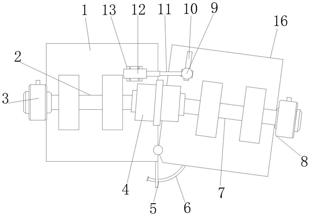
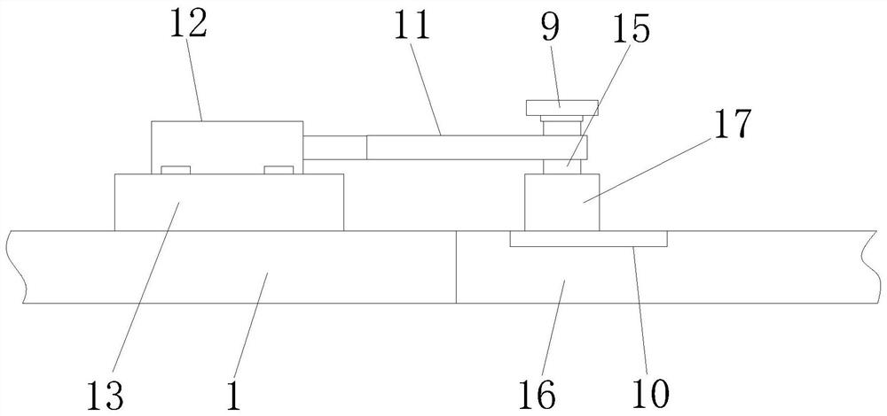
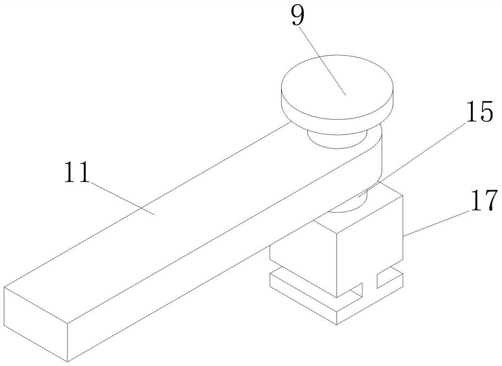
[0020] see Figure 1-4 , the present invention provides the following technical solutions: a permanent magnet coupling test bench control system, including a left stand 1, one end of the left stand 1 is provided with a power mechanism 3, and the output end of the power mechanism 3 is provided with a power input shaft 2 , the side of the left stand 1 away from the power mechanism 3 is provided with a right stand 16, and the end of the right stand 16 away from t...


PUM


Abstract

The invention discloses a permanent magnet coupler test bed control system, and belongs to the technical field of coupler test equipment. The system comprises a left rack, a power mechanism is arranged at one end of the left rack, a power input shaft is arranged at the output end of the power mechanism, and a right rack is arranged on one side, far away from the power mechanism, of the left rack. A resistance mechanism is arranged at one end, far away from the power mechanism, of the right rack, and a resistance input shaft is arranged at the output end of the resistance mechanism, an electric push rod is arranged, a connecting rod is pushed through the electric push rod, and the connecting rod drives a sliding seat at the lower end to slide in a sliding groove in the right rack through a fixing rod; the angle between the right rack and the left rack is changed, the coupling can be conveniently experimented, the practicability of the device is improved, meanwhile, the electric push rod is connected with the left rack through the mounting seat, and the upper end of the fixing rod is in threaded connection with the limiting sleeve, so that the device can be conveniently mounted and dismounted.

Description

technical field [0001] The invention belongs to the technical field of shaft coupling test equipment, and in particular relates to a control system of a permanent magnet coupling test bench. Background technique [0002] Couplings are used to connect two shafts (drive shaft and driven shaft) in different mechanisms to make them rotate together to transmit torque mechanical parts. In high-speed and heavy-duty power transmission, some couplings also have the functions of buffering, damping and improving the dynamic performance of the shafting. The coupling consists of two halves, which are respectively connected to the driving shaft and the driven shaft. Generally, the power machine is mostly connected with the working machine by means of a coupling. [0003] The Chinese patent application number is CN102323065 A discloses a coupling test method and a test bench, the equipment is inconvenient to adjust the angle of the left bench and the right bench, and it cannot be observe...

Claims


Application Information

Patent Timeline
Patent Type & Authority Applications(China)
IPC IPC(8): G01M13/022
CPCG01M13/022
Inventor 宋子越
Owner 嘉兴美茵钛传动科技有限公司
Learn More