
A time-frequency domain full waveform inversion method and device using a normalized seismic source

A full-waveform inversion and normalization technology, applied in measurement devices, seismology, seismic signal processing, etc., can solve problems such as reduced inversion accuracy, incorrect update of structural interface, inability to decouple normalized frequency characteristics, etc. To achieve the effect of eliminating the wavelet effect and weakening the limitation

Active Publication Date: 2022-02-18
CHINA UNIV OF MINING & TECH
View PDF9 Cites 0 Cited by
  • Summary
  • Abstract
  • Description
  • Claims
  • Application Information

AI Technical Summary

Problems solved by technology

However, due to the needs of data simulation, the frequency contained in the wavelet has a certain amplitude distribution, that is, only the frequency update near the main frequency is dominant, and the update of more low-frequency information cannot be guaranteed; at the same time, it is impossible to calculate the gradient. Decoupling and normalizing the frequency features, so there is a wavelet effect in the full waveform inversion, and there will be a phenomenon of wrong update at the structural interface, which reduces the inversion accuracy to a certain extent; even if the multi-scale method is used, this subwave Wave effects also accompanies the entire inversion, leading to over-updating at the high-contrast boundaries of structures

Method used


Image

  • A time-frequency domain full waveform inversion method and device using a normalized seismic source
  • A time-frequency domain full waveform inversion method and device using a normalized seismic source
  • A time-frequency domain full waveform inversion method and device using a normalized seismic source

Examples


Embodiment Construction

[0065] The following will clearly and completely describe the technical solutions in the embodiments herein in conjunction with the accompanying drawings in the embodiments herein. Obviously, the described embodiments are only some of the embodiments herein, not all of them. Based on the embodiments herein, all other embodiments obtained by persons of ordinary skill in the art without making creative efforts fall within the scope of protection herein.

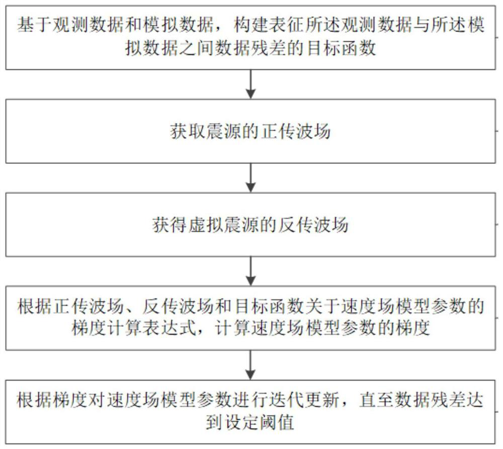
[0066] Such as figure 1 As shown, the inversion method of the embodiment of the present invention includes:

[0067] S1: Use the known observation system to receive the observation data fed back after the source is excited; establish the velocity field model, and calculate the simulated data according to the condition of the source;

[0068] S2: Based on the observed data and the simulated data, construct an objective function characterizing the data residual between the observed data and the simulated data;

[0069] The obje...


PUM


Abstract

The invention discloses a time-frequency domain full-waveform inversion method and device using a normalized seismic source. The seismic source is a plurality of single-frequency signals extracted from known wavelets and the amplitudes are normalized, which is completed in the time domain. The wave field simulation of multiple normalized single-frequency seismic sources extracted; and the phase-sensitive detection method is used to decouple the forward wave field and the reverse wave field respectively, so as to obtain the amplitude and phase information of the wave field through decoupling , in order to eliminate the limitation of each frequency amplitude by the conventional band-limited wavelet amplitude spectrum in the inversion process, and then calculate the gradient of the velocity field model parameters according to the amplitude and phase information of the wave field and the gradient calculation expression, which is conducive to obtaining accurate The update direction of the velocity field model parameters, so as to achieve the purpose of simultaneous inversion of multiple frequencies in the inversion. The invention can weaken the limitation of the single-frequency signal amplitude by the wavelet amplitude spectrum in the conventional inversion, eliminate the wavelet effect in the inversion, realize the inversion result of spectrum whitening, and finally obtain the high-precision inversion result.

Description

technical field [0001] The invention relates to a time-frequency domain full waveform inversion method and device using a normalized seismic source, and belongs to the technical field of seismic exploration velocity modeling. Background technique [0002] As oil exploration shifts to deep and ultra-deep layers, high-precision imaging of steep and complex structures in deep target layers has become an imminent bottleneck restricting oil exploration and development. Velocity modeling is the soul of complex structural imaging, and traditional velocity modeling techniques such as velocity tomography inversion have achieved great success in the past few decades, but they can no longer meet the needs of high-resolution seismic imaging. Therefore, it is urgent to develop a new generation of velocity modeling technology to meet the needs of imaging complex structures. [0003] At present, full waveform inversion (Full Waveform Inversion, FWI) is recognized as the most potential new...

Claims


Application Information

Patent Timeline
Patent Type & Authority Patents(China)
IPC IPC(8): G01V1/28G01V1/30
CPCG01V1/282G01V1/303G01V2210/67
Inventor 方金伟刘盛东张庆臣王勃章俊王宁
Owner CHINA UNIV OF MINING & TECH
Learn More