Stable anti-skid mouse

A non-slip, mouse technology, used in instruments, computing, electrical and digital data processing, etc., can solve the problem of easy sliding of the scroll wheel, and achieve the effects of avoiding pain, simple structure and low cost.

Active Publication Date: 2021-07-23
梅州市嘉腾辉电子科技有限公司
View PDF4 Cites 1 Cited by
  • Summary
  • Abstract
  • Description
  • Claims
  • Application Information

AI Technical Summary

Problems solved by technology

[0005] The purpose of the present invention is to solve the problem that the scroll wheel in the above mouse is easy to slide when pressed, and to provide a stable non-slip mouse that prevents the scroll wheel from sliding when pressed

Method used


Image

  • Stable anti-skid mouse
  • Stable anti-skid mouse
  • Stable anti-skid mouse

Examples


Embodiment 1

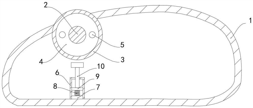
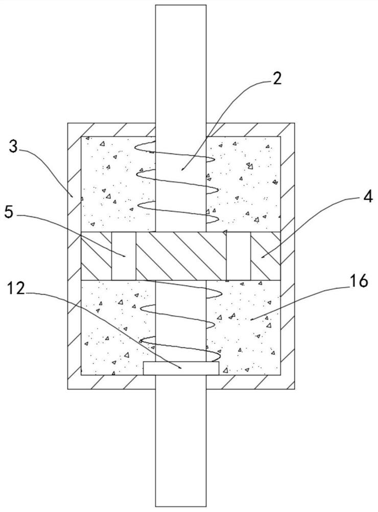
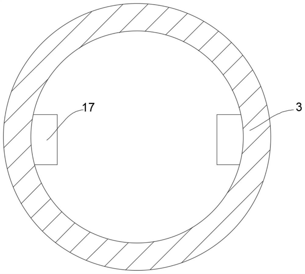
[0026] Such as Figure 1-4 As shown, a stable non-slip mouse includes a casing 1, the inner wall of the casing 1 is fixedly connected with a rotating shaft 2, the rotating shaft 2 is provided with threads and is rotatably connected with a roller 3, and a cavity is provided inside the roller 3 and a current is provided. The electrorheological fluid 16 is equipped with a conductive sheet 12, and the inner wall of the roller 3 is slidably connected with a slider 4. It is worth noting that the inner wall of the roller 3 is fixedly connected with a plurality of limit blocks 17, and the slider 4 The side wall is provided with a plurality of limit grooves 18, the limit block 17 is slidingly connected with the limit groove 18, the slider 4 is provided with a plurality of through holes 5, the slider 4 is threaded with the rotating shaft 2, and the inner side of the housing 1 The lower wall is fixedly connected with a sliding sleeve 6. It should be noted that the inner wall of the slidi...

Embodiment 2

[0030] Such as Figure 5-6 As shown, the difference between this embodiment and Embodiment 1 is that: the lower surface of the housing 1 is embedded with two anti-slip sleeves 11, the inner upper wall of the anti-slip sleeve 11 is fixedly connected with a bar magnet 13, and the bar magnet 13 The lower surface is fixedly connected with a second spring 14, and the lower surface of the anti-slip sleeve 11 is provided with an elastic layer 15. It is worth noting that the elastic layer 15 is made of rubber material, and the second spring 14 is made of nickel-titanium alloy material. The lower end of the spring 14 is fixedly connected with the elastic layer 15. It should be noted that the lower surface of the elastic layer 15 is provided with anti-skid sand, and the anti-skid sand is silicon carbide. The elastic layer 15 is embedded with a magnetic block 19, a bar magnet 13 and a magnetic The opposite poles of the blocks 19 are opposite. By setting the magnetic block 19 and the bar ...


PUM


Abstract

The invention belongs to the related field of electronics, and particularly relates to a stable anti-skid mouse which comprises a shell, a rotating shaft is fixedly connected to the inner side wall of the shell, a thread is arranged outside the rotating shaft, the rotating shaft is rotationally connected with a roller, a cavity is formed in the roller, electrorheological fluid is arranged in the cavity, a conducting strip is arranged in the electrorheological fluid. A sliding block is slidably connected to the inner side wall of the roller, a plurality of through holes is formed in the sliding block, the sliding block is in threaded connection with the rotating shaft, a sliding sleeve is fixedly connected to the lower wall of the inner side of the shell, a piezoelectric plate is fixedly connected to the lower wall of the inner side of the sliding sleeve, and the conductive plate is electrically connected with the piezoelectric plate. The upper surface of the piezoelectric sheet is fixedly connected with a spring, and the upper end of the spring is fixedly connected with a vibrating sheet. The vibrating sheet and the piezoelectric sheet are arranged, resistance borne by rotation of the roller is automatically adjusted, operation is prevented from being affected by the resistance, the magnetic block is arranged, resistance borne by movement of the mouse in the state that the roller is pressed is reduced, and hand ache is avoided.

Description

technical field [0001] The invention belongs to the related field of electronics, and in particular relates to a stable anti-slip mouse. Background technique [0002] The mouse is one of the external input devices of the computer. It is also an indicator used to locate the horizontal and vertical coordinates in the display system of the computer. The mouse is named for its shape resembling a mouse. The operation is simpler and faster, replacing many tedious operations. [0003] In the process of using the mouse to draw, we often press the scroll wheel in the middle of the mouse and drag the mouse at the same time to complete some operations, and the scroll wheel will rotate slightly while being pressed, and a little carelessness will cause improper operation. In order to avoid the occurrence of the above situation, the hand needs to exert a large force to keep the scroll wheel still, and the muscles need to be kept in a tense state, and when the hand presses the scroll whee...

Claims


Application Information

Patent Timeline
Patent Type & Authority Applications(China)
IPC IPC(8): G06F3/0354
CPCG06F3/0354
Inventor 孙爱东
Owner 梅州市嘉腾辉电子科技有限公司
Why Eureka
Try Eureka