Continuous casting method for steel

A slab and cooling zone technology, applied in the field of continuous casting of steel, can solve problems such as surface cracking, and achieve the effects of suppressing slab surface cracking, surface cracking, and water accumulation

Active Publication Date: 2021-07-23
NIPPON STEEL CORP
View PDF17 Cites 0 Cited by
  • Summary
  • Abstract
  • Description
  • Claims
  • Application Information

AI Technical Summary

Problems solved by technology

However, along with the addition of these alloy elements, surface cracking defects occur in the slab produced by continuous casting, which becomes a problem in terms of handling and product quality.

Method used


Image

  • Continuous casting method for steel
  • Continuous casting method for steel
  • Continuous casting method for steel

Examples


Embodiment

[0064] Hereinafter, examples are shown, and the continuous casting method of steel according to the present invention will be described in more detail.

[0065] 1. Experimental conditions

[0066] A slab with a width of 2200 mm and a thickness of 300 mm was produced using a vertical bending type continuous casting apparatus. The steel type was set to be a low-alloy steel having a composition (mass %) shown in Table 1 and having a high cracking sensitivity.

[0067] It should be noted that the Ac of steel types A and B 3 The point temperatures were 898°C and 872°C, respectively.

[0068] Table 1

[0069] C Si mn P S Cu Ni Cr Al Nb Ti N A 0.06 0.5 1.6 0.01 0.004 0.25 0.35 0.02 0.02 0.015 0.001 0.004 B 0.12 0.2 1.2 0.008 0.003 0.30 0.08 0.3 0.03 0.015 0.015 0.004

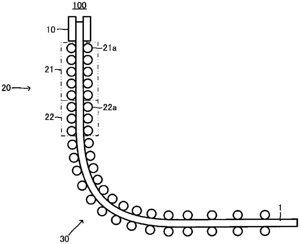
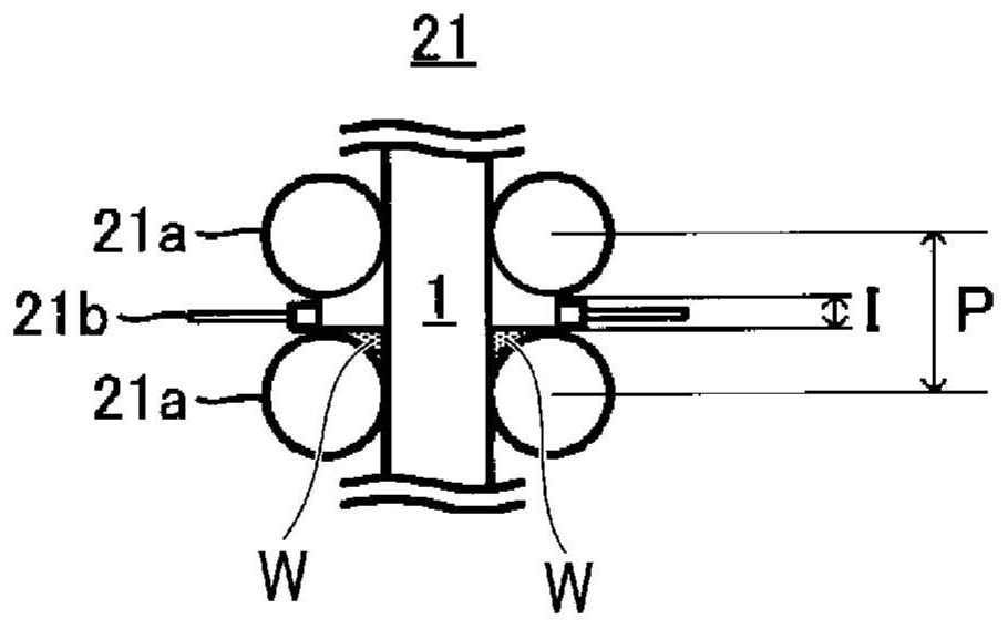
[0070] In the secondary cooling zone of the continuous casting device, 15 spray nozzles are installed at intervals of 150 mm in the width direction of...


PUM


Abstract

The invention relates to a continuous casting method for steel. In a first cooling zone (21) on the upper side of a vertical section (20), an air-water ratio A1 / R1 defined by a water amount R1 (L / min) and an air amount A1 (L / min) per one cooling spray nozzle is set to 10 or more, an impinging pressure of cooling water colliding with the surface of a slab (1) from the cooling spray nozzle is set to 12 gf / cm2 or more, a cooling intensity W1 * t1 defined by a cooling water density W1 (L / min / m<2>) and a passing time t1 (min) of the first cooling zone (21) is set to 350 or more, and a reheating time from the passage of the first cooling zone (21) to a bent portion (30) is set to 0.5 min or more.

Description

technical field [0001] The invention relates to a continuous casting method of steel. [0002] This application claims priority based on Japanese Patent Application No. 2018-231136 for which it applied in Japan on December 10, 2018, and uses the content here. Background technique [0003] In recent years, among iron and steel materials such as thick steel plates, many low-alloy steels containing alloy elements such as Ti, Nb, Ni, and Cu have been produced in order to improve mechanical properties. However, along with the addition of these alloy elements, surface cracking defects occur in slabs produced by continuous casting, which poses a problem in terms of handling and product quality. Surface cracking here is a general term for cracking forms in non-casting directions such as transverse cracks. [0004] As a method for preventing surface cracking of a slab containing alloy elements during continuous casting, there is a method disclosed in Patent Document 1, for example....

Claims


Application Information

Patent Timeline
Patent Type & Authority Applications(China)
IPC IPC(8): B22D11/124B22D11/22
CPCB22D11/124B22D11/22B22D11/1246B22D11/1245
Inventor 高屋慎村上敏彦
Owner NIPPON STEEL CORP
Why Eureka
Try Eureka