Systems and methods for determining coil current in wireless power systems
A wireless power and coil technology, applied in the direction of voltage/current isolation, current only measurement, current/voltage measurement, etc., can solve problems such as difficult current measurement
- Summary
- Abstract
- Description
- Claims
- Application Information
AI Technical Summary
Problems solved by technology
Method used
Image
Examples
no. 1 example
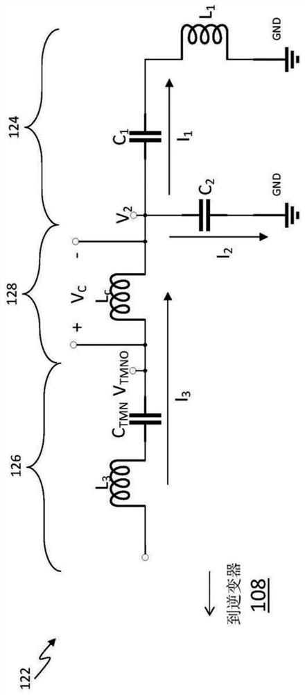
[0060] Used to determine coil current I 1 The first exemplary embodiment of the system and / or method can use the following derivation:
[0061]
[0062]
[0063]
[0064]
[0065]
[0066]
[0067]
[0068] Figure 3A Is used to determine the coil current I 1 A block diagram of the first exemplary system and / or method. The exemplary system and / or method 300 perform step 1.7 exported by electronic signals and / or components (eg, in hardware and / or software). Specifically, in the upper branch, current sense transformer 302 receives current I 3 And generate with current I 3 Based output voltage V I3CS . This voltage signal V I3CS Then filter in the band pass filter 304 to produce a voltage signal V. I3CS The voltage signal V of the fundamental frequency component V I3M . In block 306, voltage signal V I3M Zoom L C C 2 Ω 2 . Voltage signal V I3M It is also scaled by block 308 for from current I 3 The total gain matching of the positive input of the subtraction fra...
no. 2 example
[0072] Used to determine coil current I 1 The second exemplary embodiment of the system and / or method can use the following derivation:
[0073]
[0074]
[0075]
[0076]
[0077] Figure 4 Is used to determine the coil current I 1 A block diagram of the second exemplary system and / or method. The exemplary system and / or method 400 implements step 2.4 derived by electronic signals and / or components (e.g., in hardware and / or software). Specifically, in the upper branch, current sensing transformer 402 receives current I 3 And generate with current I 3 Based output voltage V I3CS . This voltage signal V I3CS Then filter in the band pass filter 404 to produce a voltage signal V. I3CS The voltage signal V of the fundamental frequency component V I3M . In block 406, voltage signal V I3M Differential and l C Zoom. Voltage signal V I3M Also zoom at block 408 so as to be from current I 3 The total gain matching of the subtraction frame 420 is from current I 2 The total g...
no. 3 example
[0079] Used to determine coil current I 1 The third exemplary embodiment of the system and / or method can use the following derivation:
[0080] I 1 = I 3 -I 2 (3.1)
[0081]
[0082]
[0083]
[0084] Figure 5 Is used to determine the coil current I 1 A block diagram of the third exemplary system and / or method. The exemplary system and / or method 500 perform step 3.4 exported by electronic signals and / or components (eg, in hardware and / or software). Specifically, in the upper branch, current sensing transformer 502 receives current I 3 And generate with I 3 Based output voltage V I3CS . In block 504, this voltage signal V I3CS Differential and being l C Zoom. Voltage signal V I3M The block 506 is also zoomed in order to 3 The total gain matching of the positive input of the subtraction frame 518 is from I 2 The total gain of the negative input of the subtraction frame 518. In the lower branch, the capacitive voltage divider 508 receives the output voltage V. TMNO G...
PUM
 Abstract
Description
Claims
Application Information
 - R&D Engineer
- R&D Manager
- IP Professional
- Industry Leading Data Capabilities
- Powerful AI technology
- Patent DNA Extraction
Browse by: Latest US Patents, China's latest patents, Technical Efficacy Thesaurus, Application Domain, Technology Topic.
© 2024 PatSnap. All rights reserved.Legal|Privacy policy|Modern Slavery Act Transparency Statement|Sitemap


