Differential pressure type flowmeter

A technology of differential pressure flowmeter and differential pressure sensor, which is applied in the direction of volume measurement, flow/mass flow measurement, liquid/fluid solid measurement, etc., and can solve the problems of large flow measurement error and differential pressure measurement error, etc. Achieve the effect of reducing pressure measurement error and flow measurement error

Inactive Publication Date: 2021-07-27
YAMATAKE HONEYWELL CO LTD
View PDF2 Cites 0 Cited by
  • Summary
  • Abstract
  • Description
  • Claims
  • Application Information

AI Technical Summary

Problems solved by technology

[0016] But when Figure 16 ~ Figure 18 In the configuration shown, the measured pressure upstream and downstream of the laminar flow element 100 is affected by the temperature measurement error of the temperature sensors 103 and 104, so the differential pressure measurement error becomes large, and as a result, the flow rate measurement error may become large. sex
[0017] The above problems are not limited to laminar flow meters, but also occur in differential pressure flow meters using orifice plates, pitot tubes, etc. as differential pressure generating mechanisms.

Method used


Image

  • Differential pressure type flowmeter
  • Differential pressure type flowmeter
  • Differential pressure type flowmeter

Examples


no. 1 example

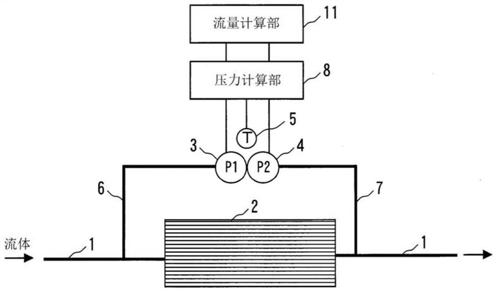
[0057] Hereinafter, embodiments of the present invention will be described with reference to the drawings. figure 1 It is a diagram showing the configuration of a laminar flow meter (differential pressure flow meter) according to a first embodiment of the present invention. The laminar flow type flowmeter includes: a pipe 1 that allows the fluid to be measured to circulate; a laminar flow element 2 that is installed in the pipe 1 and is a differential pressure generating mechanism that generates a differential pressure between the fluid on the upstream side and the fluid on the downstream side; Absolute pressure sensor 3, which measures the absolute pressure P1 of the fluid on the upstream side of the laminar flow element 2; an absolute pressure sensor 4, which measures the absolute pressure P2 of the fluid on the downstream side of the laminar flow element 2; a temperature sensor 5, which measures the absolute pressure sensor 3 , the ambient temperature of 4; conduits 6, 7, ...

no. 2 example

[0081] Next, a second embodiment of the present invention will be described. Image 6 It is a diagram showing the configuration of a laminar flow meter (differential pressure flow meter) according to a second embodiment of the present invention. The laminar flow meter of this embodiment includes: a pipe 1, a laminar flow element 2, a differential pressure sensor 9 for measuring the differential pressure ΔP of the fluid on the upstream side and downstream side of the laminar flow element 2, and a pressure sensor 9 for measuring the downstream side of the laminar flow element 2. Absolute pressure sensor 4, temperature sensor 5, conduits 6, 7 of the absolute pressure P2 of the fluid, based on the temperature T measured by the temperature sensor 5, the output signal of the differential pressure sensor 9 is corrected and converted into a differential pressure ΔP, and based on the temperature T corrects the output signal of the absolute pressure sensor 4 and converts it into an abso...

no. 3 example

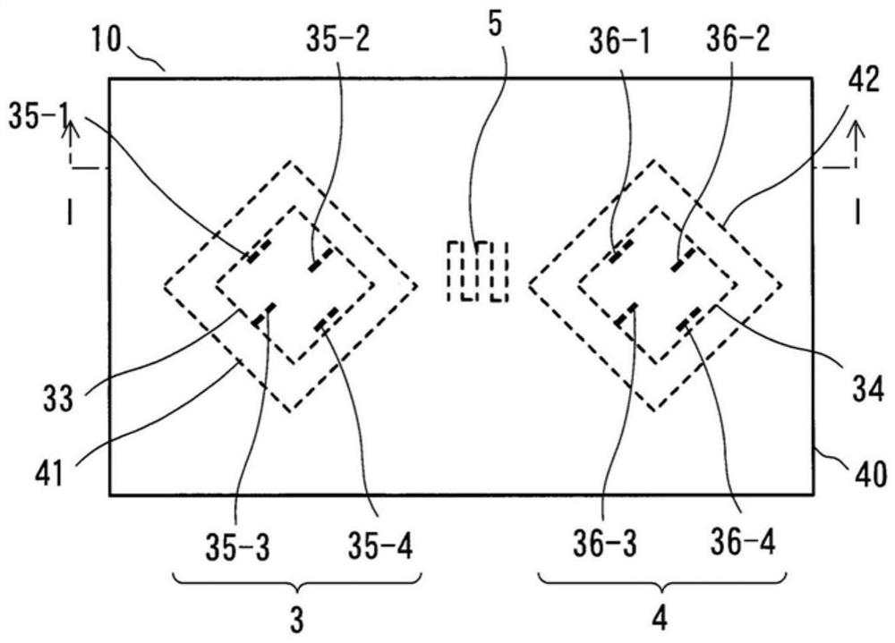
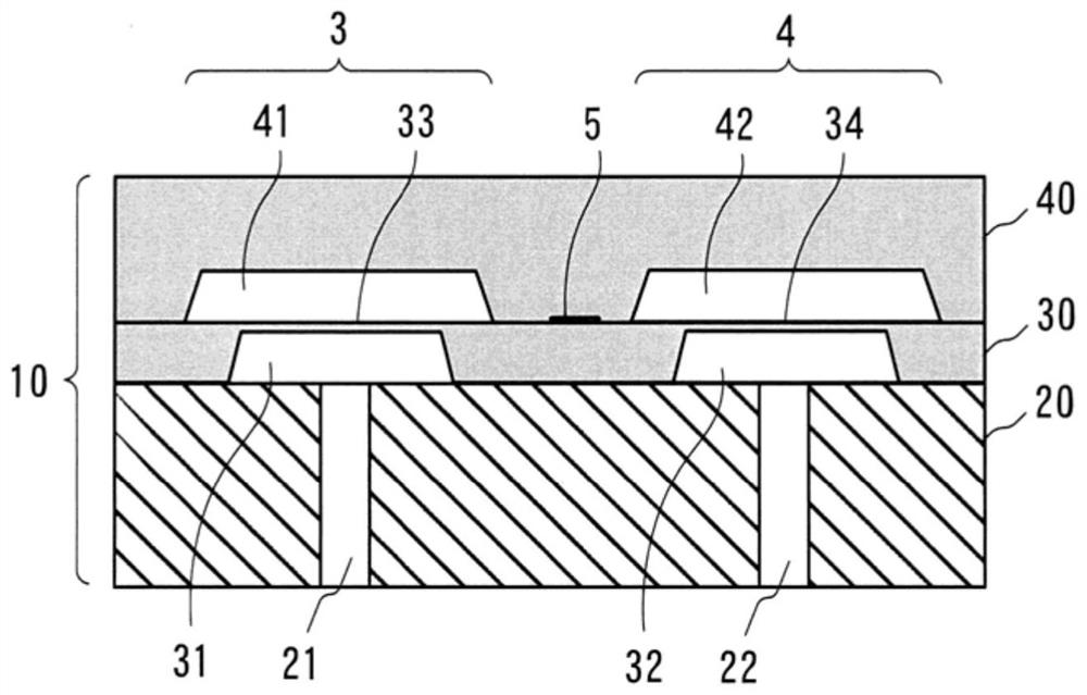
[0103] In the first and second embodiments, the two diaphragms for pressure detection and the temperature sensor are integrated on one chip, but it is also possible to house the two sensor chips and the temperature sensor in the same package. Figure 10 It is a top view of a sensor package of a laminar flow meter (differential pressure flow meter) according to a third embodiment of the present invention, Figure 11 yes Figure 10 I-I line sectional view. In addition, in Figure 10 In , the inside of the sensor package is shown transparently for easy observation of the structure.

[0104] The piping 1, the laminar flow element 2, the conduits 6, 7, the pressure calculation unit 8, and the flow rate calculation unit 11 are the same as those described in the first embodiment, and the laminar flow meter of this embodiment corresponds to figure 1 A device obtained by replacing the temperature sensor 5 with the temperature sensor 5b.

[0105] For example, the sensor chip 10 b o...


PUM


Abstract

A differential pressure type flowmeter which can reduce a flow rate measurement error includes: a pipe (1); a laminar flow element (2) disposed within the pipe (1); a first absolute pressure sensor (3) measuring an absolute pressure (P1) of a fluid upstream of the laminar flow element (2); a second absolute pressure sensor (4) measuring an absolute pressure (P2) of the fluid downstream; a temperature sensor (5) measuring an ambient temperature (T) of the absolute pressure sensors (3, 4); a pressure calculation section (8) correcting an output signal from the first absolute pressure sensor (3) based on the temperature (T) to be converted into the absolute pressure (P1), and correcting an output signal from the second absolute pressure sensor (4) based on the temperature (T) to be converted into the absolute pressure (P2); and a flow rate calculation section (11) calculating a flow rate of the fluid based on the absolute pressures (P1) and (P2) calculated by the pressure calculation section (8). A film of the absolute pressure sensor (3) bearing absolute pressure (P1) and a film of the absolute pressure sensor (4) bearing absolute pressure (P2), and the temperature sensor (5) are integrated in one sensor chip.

Description

technical field [0001] The present invention relates to differential pressure flowmeters such as laminar flowmeters. Background technique [0002] A laminar flow meter utilizes a phenomenon in which a pressure drop accompanying fluid movement is proportional to a volume flow rate when the fluid flows in a laminar flow state in a pipe (see Patent Document 1 and Patent Document 2). The relationship between fluid passing through a laminar flow element and the resulting differential pressure ΔP is generally expressed by the following equation. [0003] Qm=ΔP×π×d 4 ×ρ / (128×μ×L)···(1) [0004] In formula (1), Qm is the mass flow rate, d is the flow path diameter of the laminar flow element, L is the flow path length of the laminar flow element, μ is the viscosity coefficient of the fluid, and ρ is the density of the fluid. [0005] Such as Figure 15 As shown, in the laminar flow meter, the absolute pressure sensors 101, 102 are arranged upstream and downstream of the laminar f...

Claims


Application Information

Patent Timeline
Patent Type & Authority Applications(China)
IPC IPC(8): G01F1/34
CPCG01F1/34G01F1/363G01F1/40G01F15/00G01F1/386G01F1/42G01F1/383G01F1/46
Inventor 结城兴仁东条博史木田希
Owner YAMATAKE HONEYWELL CO LTD
Why Eureka
Try Eureka