Automatic mine burying equipment in war area

An automatic and equipment technology, applied in the direction of motor vehicles, manipulators, tracked vehicles, etc., can solve problems such as danger

Inactive Publication Date: 2021-07-30
王欢
View PDF0 Cites 0 Cited by
  • Summary
  • Abstract
  • Description
  • Claims
  • Application Information

AI Technical Summary

Problems solved by technology

[0002] Laying a large number of landmines in the combat area can effectively prevent enemy penetration, but laying landmines through infantry is a more dangerous task, because infantry may be attacked by enemy snipers or artillery, so an automatic equipment for laying mines

Method used


Image

  • Automatic mine burying equipment in war area
  • Automatic mine burying equipment in war area
  • Automatic mine burying equipment in war area

Examples


Embodiment Construction

[0024] The technical solutions of the present invention will be further specifically described below through the embodiments and in conjunction with the accompanying drawings. In the following description, many specific details are set forth in order to fully understand the present invention, but the present invention can be implemented in many other ways different from those described here, and those skilled in the art can do similar Modifications, and therefore the present invention is not limited to the specific examples disclosed below.

[0025]In the description of the present invention, it should be noted that the orientation or positional relationship indicated by the terms "up", "down", "front", "rear", "left", "right" etc. are based on the Orientation or positional relationship, or the orientation or positional relationship that the inventive product is usually placed in use, is only for the convenience of describing the present invention and simplifying the descripti...


PUM


Abstract

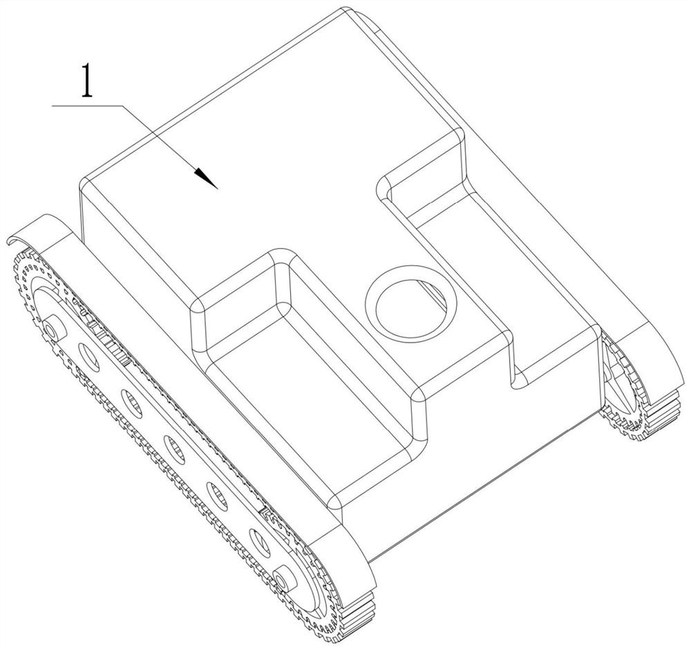
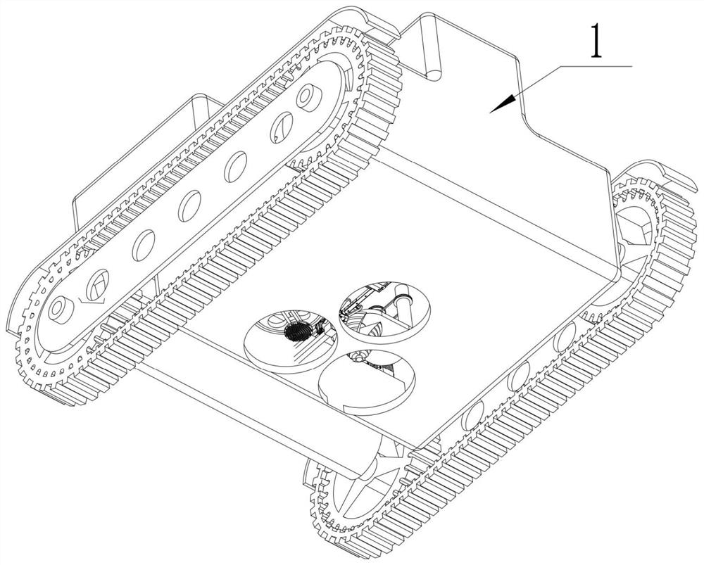
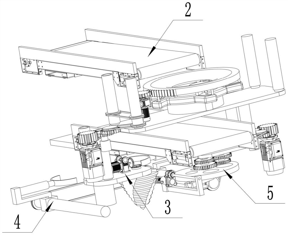
Automatic mine burying equipment in a war area comprises a shell, a conveying and lifting part, a pit digging part, a mine burying safety opening part and a soil burying part. The conveying and lifting part can transmit the landmine to a designated position. The pit digging part can be used for digging a pit in which a landmine can be buried. The mine burying safety opening part can be used for putting the landmine into a pit and opening a safety on the landmine. The soil burying part can be used for filling a pit in which the landmine is buried and troweling the soil. An electric cylinder in an electric cylinder supporting table works to drive a landmine to descend to a designated position, an electric cylinder clamp works to clamp the landmine, a servo motor C drives a fuse to be pulled open, then the electric cylinder clamp puts the landmine into a pit, and automation of mine burying is achieved. According to the automatic mine burying equipment in the war area, mine burying is fully automatic, and the danger caused by mine burying of infantries is avoided.

Description

technical field [0001] The invention relates to the field of military technology, in particular to an automatic mine-burying device in a war zone. Background technique [0002] Planting a large number of landmines in the combat area can effectively prevent the enemy from infiltrating, but laying mines through infantry is a more dangerous task, because infantry may be attacked by enemy snipers or artillery, so an automatic Equipment for laying mines. Contents of the invention [0003] In view of the above technical problems, the present invention provides an automatic mine-burying device in a war zone, which fully automates mine-laying and avoids the danger caused by infantry mine-burying. [0004] The technical solution used in the present invention is: an automatic mine-burying device in a war zone, including: a casing, a transmission lifting part, a digging part, a mine opening insurance part, and a soil-burying part; There are multiple round holes, and crawlers are pr...

Claims


Application Information

Patent Timeline
IPC IPC(8): B25J5/00B25J11/00B25J19/00B62D55/18
CPCB25J5/005B25J11/002B25J19/00B62D55/18
Inventor 王欢
Owner 王欢
Why Eureka
Try Eureka