Concrete grouting device for building construction

A building construction and concrete technology, which is applied in the direction of construction, building structure, and building material processing, etc. It can solve the problems of slowing down the concrete grouting speed and sand clusters stuck inside the feeding pipe, etc.

Pending Publication Date: 2021-07-30
THE SECOND CONSTR ENG CO LTD OF CHINA CONSTR THIRD ENG BUREAU
View PDF0 Cites 0 Cited by
  • Summary
  • Abstract
  • Description
  • Claims
  • Application Information

AI Technical Summary

Problems solved by technology

[0003] In order to solve the above problem that when the grouting bucket is used for pouring concrete materials in construction, when the concrete material is not stirred uniformly, the material contains sand, and the end of the delivery pipe is at a horizontal angle, which is prone to the phenomenon that the sand is stuck inside the delivery pipe , causing the concrete grouting speed to slow down, the invention provides a concrete grouting device for building construction

Method used


Image

  • Concrete grouting device for building construction
  • Concrete grouting device for building construction
  • Concrete grouting device for building construction

Examples


Embodiment 1

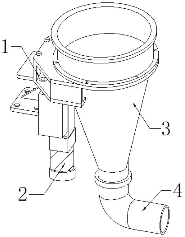
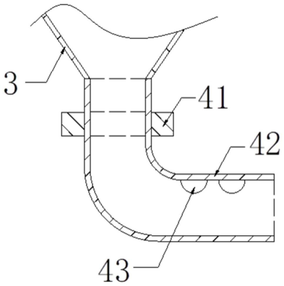
[0029] Such as Figure 1 to Figure 5 Shown: the present invention provides a kind of concrete grouting device for building construction, and its structure comprises fixed block 1, vibrator 2, hopper 3, feeding pipe 4, and described vibrator 2 top is connected with fixed block 1 bottom surface by bolt, so The left side of the hopper 3 is welded to the right end surface of the fixed block 1, and the top of the feeding pipe 4 is connected to the bottom of the hopper 3 . Such as figure 2 As shown, the feeding pipe 4 includes a connection block 41, a pipe body 42, and a dispersing mechanism 43. The pipe body 42 is nested in the middle of the connection block 41 near the top end, and the top of the dispersing mechanism 43 is installed on the pipe body 42 near the top. At the inner top position of the right end, the top of the pipe body 42 communicates with the bottom of the hopper 3 .

[0030] Such as image 3 As shown, the dispersing mechanism 43 includes a support block 431, t...

Embodiment 2

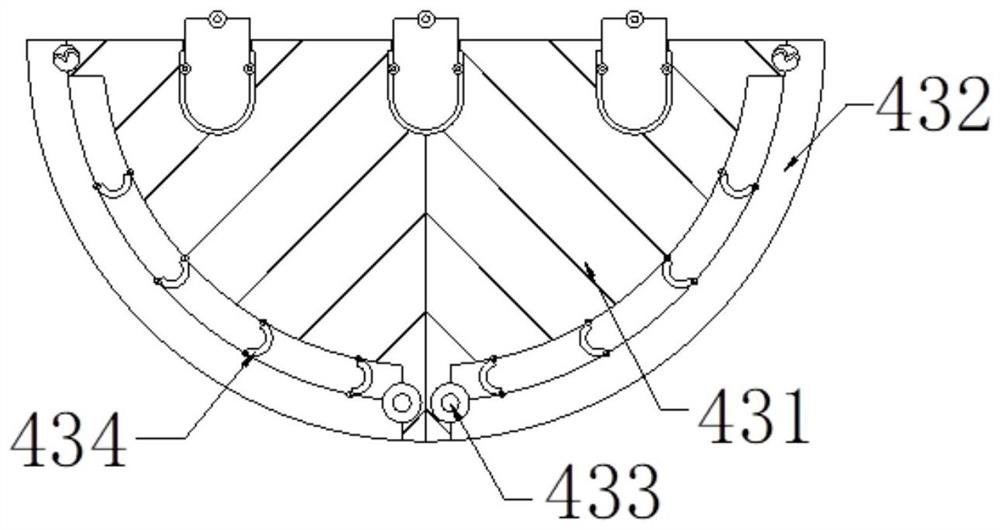
[0036] Such as Image 6 As shown, the support block 431 includes an engaging block 31a, three engaging grooves 31b, three engaging rods 31c, an inner groove 31d, and a sliding ball 31e, each engaging groove 31b is recessed on the top surface of the engaging block 31a from top to bottom, each The bottom end of the connecting rod 31c is enclosed within a draw-in groove 31b, and an inner groove 31d is arranged at the inner bottom of the connecting block 31a. The sliding ball 31e is located inside the inner groove 31d and can slide. On the tube body 42. The support block 431 is suspended on the inner bottom of the pipe body 42 through the connecting rod 31c, which is beneficial for the supporting block 431 to swing left and right under the thrust of the material flow, which can push the material and accelerate the discharge speed of the material. There are three connecting rods 31c, It is beneficial to increase the support force received by the support block 431, reduce the pheno...


PUM


Abstract

The invention discloses a concrete grouting device for building construction. The device comprises a fixing block, a vibrator, a hopper and a material conveying pipe; the top of the vibrator is connected with the bottom face of the fixing block through a bolt; the left side face of the hopper is welded to the surface of the right end of the fixing block; the top of the material conveying pipe is connected with the bottom end of the hopper; the device is characterized in that the material conveying pipe comprises a connecting block, a pipe body and a dispersing mechanism; the portion, close to the top end, of the pipe body is nested in the middle of the connecting block; the top of the dispersing mechanism is installed at the position, close to the right end, of the inner top of the pipe body; and the top end of the pipe body communicates with the bottom end of the hopper. Materials are impacted and dispersed through thrust swing of a dispersing plate of the dispersing mechanism in the pipe body, so that sand balls jammed in the conveying pipe are reduced, and the concrete grouting speed is increased. A supporting block of the dispersing mechanism swings left and right and moves up and down under the thrust of the materials, so that the materials can be pushed to increase the discharging speed of the materials, and the supporting block can move up and down conveniently to drive the dispersing plate to continuously impact the materials.

Description

technical field [0001] The invention belongs to the technical field of building construction, and more specifically relates to a concrete grouting device for building construction. Background technique [0002] The building construction uses a grouting hopper to grout the formwork with small gaps. The concrete material is passed into the hopper, and the concrete material flows along the feeding pipe and is discharged into the gap between the formworks. The grouting hopper is equipped with a vibrator. The start-up makes the hopper vibrate and the concrete material falls, reducing the concrete sticking to the inner wall of the hopper; in the prior art, when the grouting hopper is used for pouring concrete materials in construction, when the concrete material is not stirred uniformly, the material contains sand clusters, and the feeding The end of the pipe is at a horizontal angle, which is prone to the phenomenon that sand clusters are stuck inside the feeding pipe, which will...

Claims


Application Information

Patent Timeline
Patent Type & Authority Applications(China)
IPC IPC(8): E04G21/02
CPCE04G21/02
Inventor 宋光路刘昌平兰云睆秦凯马刚强张晓晓任治国汪兴铎肖启蒙王昶钧
Owner THE SECOND CONSTR ENG CO LTD OF CHINA CONSTR THIRD ENG BUREAU
Why Eureka
Try Eureka