Optical imaging system, image capturing module, electronic equipment and automobile

A technology of optical imaging system and optical axis, applied in optics, optical components, instruments, etc.

Inactive Publication Date: 2021-07-30
TIANJIN OFILM OPTO ELECTRONICS CO LTD
View PDF0 Cites 4 Cited by
  • Summary
  • Abstract
  • Description
  • Claims
  • Application Information

AI Technical Summary

Problems solved by technology

[0004] However, the current optical imaging system cannot meet the above requirements

Method used


Image

  • Optical imaging system, image capturing module, electronic equipment and automobile
  • Optical imaging system, image capturing module, electronic equipment and automobile
  • Optical imaging system, image capturing module, electronic equipment and automobile

Examples


no. 1 example

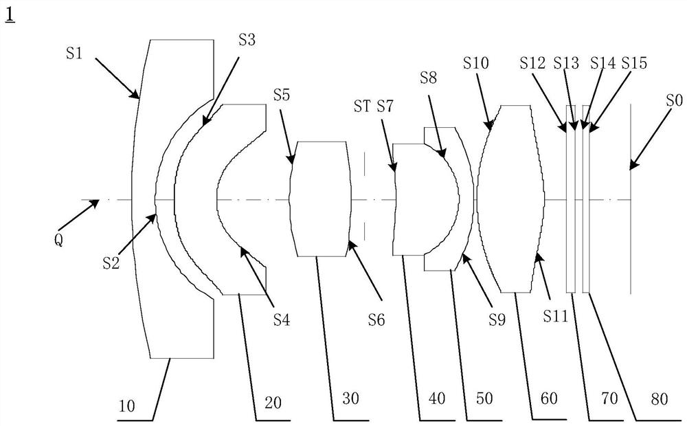
[0132] Refer figure 1 and figure 2 The optical imaging system 1 in the first embodiment includes a first lens 10 having a negative flexible force in the image side, a second lens 20 having a negative flexible force, a third lens 30 having a divergetic force. The fourth lens 40 having a divergetic force, a fifth lens 50 having a negative flexible force, a sixth lens 60, a filter 70, and a protective glass 80 having a positive flexible force.

[0133] Wherein, the side surface S1 of the first lens 10 is a convex surface at a proximal optical axis Q, and the image side surface S2 of the first lens 10 is concave in the near-optical axis Q; the side surface S3 of the second lens 20 is at the near-optical axis Q For the convex surface, the image side surface S4 of the second lens 20 is a concave surface at the near-optical axis q; the side surface S5 of the third lens 30 and the image side surface S6 are all convex surfaces; the fourth lens 40 side surface S7 The near-optical axis Q is ...

no. 2 example

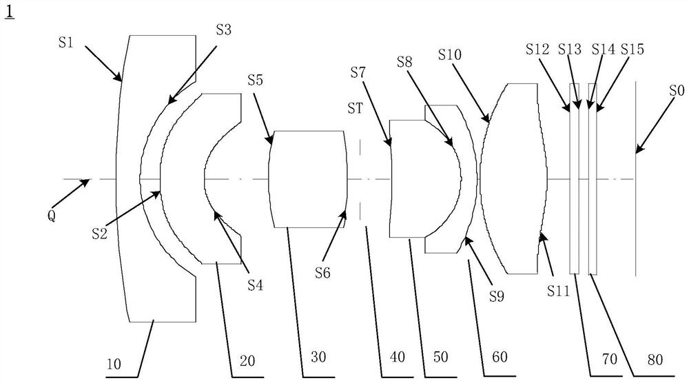
[0143] Refer image 3 and Figure 4 The optical imaging system 1 in the second embodiment sequentially includes a first lens 10 having a negative and flexible force, a second lens 20 having a ductility, and a third lens 30 having a positive flexible force. The fourth lens 40 having a divergetic force, a fifth lens 50 having a negative flexible force, a sixth lens 60, a filter 70, and a protective glass 80 having a positive flexible force.

[0144] Wherein, the side surface S1 of the first lens 10 is a convex surface at a proximal optical axis Q, and the image side surface S2 of the first lens 10 is concave in the near-optical axis Q; the side surface S3 of the second lens 20 is at the near-optical axis Q For the convex surface, the image side surface S4 of the second lens 20 is a concave surface at the near-optical axis q; the side surface S5 of the third lens 30 and the image side surface S6 are all convex surfaces; the fourth lens 40 side surface S7 The near-optical axis Q is a co...

no. 3 example

[0154] Refer Figure 5 and Image 6 , The optical imaging system 1 in the third embodiment includes a first lens 10 having a negative flexible force in the image side, a second lens 20 having a negative flexible force, a third lens 30 having a divergetic force. The fourth lens 40 having a divergetic force, a fifth lens 50 having a negative flexible force, a sixth lens 60, a filter 70, and a protective glass 80 having a positive flexible force.

[0155] Wherein, the side surface S1 of the first lens 10 is a convex surface at a proximal optical axis Q, and the image side surface S2 of the first lens 10 is concave in the near-optical axis Q; the side surface S3 of the second lens 20 is at the near-optical axis Q For the convex surface, the image side surface S4 of the second lens 20 is a concave surface at the near-optical axis q; the side surface S5 of the third lens 30 and the image side surface S6 are all convex surfaces; the fourth lens 40 side surface S7 The near-optical axis Q is...


PUM

PropertyMeasurementUnit
Maximum viewing angleaaaaaaaaaa

Abstract

The invention relates to the technical field of optical imaging, in particular to an optical imaging system, an image capturing module, electronic equipment and an automobile. The optical imaging system comprises, in order from an object side to an image side: a first lens having negative refractive power; a second lens element with negative refractive power; a third lens with positive refractive power, wherein the object side surface and the image side surface of the third lens are convex surfaces near the optical axis; a fourth lens with positive refractive power, wherein the object side surface of the fourth lens is a concave surface near the optical axis, and the image side surface of the fourth lens is a convex surface near the optical axis; a fifth lens with negative refractive power,wherein the object side surface of the fifth lens element is a concave surface near the optical axis, and the image side surface of the fifth lens is a convex surface near the optical axis; a sixth lens with positive refractive power, wherein the object side surface and the image side surface of the sixth lens are convex surfaces near the optical axis; the optical imaging system satisfies the following conditional expression: 5 < f123/f < 7. According to the optical imaging system, the imaging resolution of the system can be improved, so that the imaging quality is improved.

Description

Technical field [0001] The present application relates to the field of optical imaging, and in particular, to an optical imaging system, an image forming module, an electronic device, and a car. Background technique [0002] With the development of the in-vehicle industry, the application of ADAS and DMS's car driving, not only requires monitoring of the driver's status, according to the eye state, closing the number of eyes, closed eye, yawning, etc. It is required to monitor the status of the driving habits to fully determine the change of the driver's driving environment, thereby presented a safety warning to remind the driver's driving status and make a prevention in advance. [0003] Therefore, it is necessary to provide an optical imaging system to provide a driver, passenger's condition or a driving environment of driving ambient status, to the driving control system, so that the system makes accurate analysis and judgment, ensuring driving safety and environmental visuali...

Claims


Application Information

Patent Timeline
IPC IPC(8): G02B13/00G02B13/06G02B13/18G03B30/00
CPCG02B13/0045G02B13/006G02B13/06G02B13/18
Inventor 乐宇明蔡雄宇周宝赵迪
Owner TIANJIN OFILM OPTO ELECTRONICS CO LTD
Why Eureka
Try Eureka