dental root canal
A root canal treatment and appliance technology, applied in dentistry, medical science, tooth filling, etc., can solve problems such as poor cutting performance, out of the treatment path, and difficult operation
- Summary
- Abstract
- Description
- Claims
- Application Information
AI Technical Summary
Problems solved by technology
Method used
Image
Examples
Embodiment approach 1
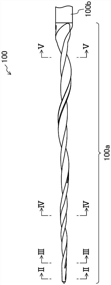
[0090] like figure 1 As shown, a dental file (dental root canal treatment instrument) 100 includes: a working part 100a for cutting the root canal; a shaft part 100b connected to the rear end of the working part 100a; and a rear end of the shaft part 100b It is attached to and attached to the not-shown grip of the dental handpiece. As the raw material of the dental file 100 , for example, high-elasticity nickel-titanium, which is suitable for the treatment of complex curved root canals, is used.
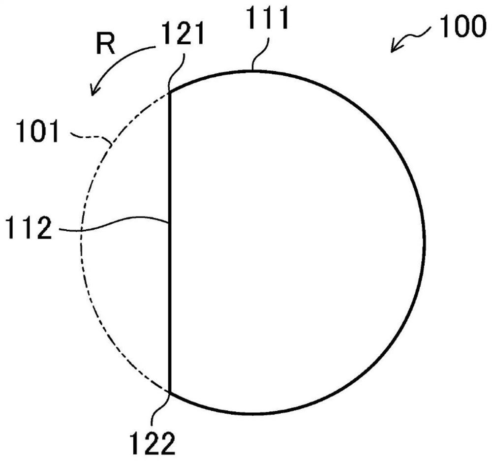
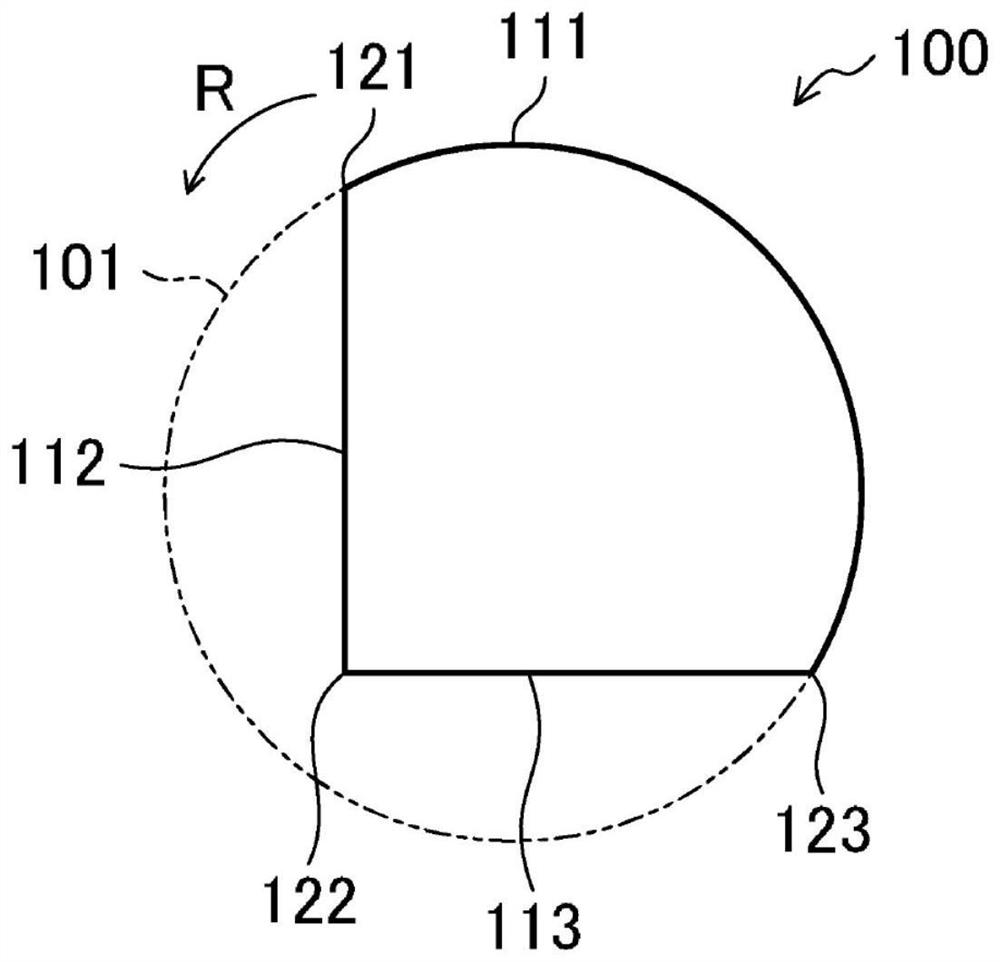
[0091] The working part 100a of the dental file 100 is configured such that the envelope surface of the outer surface has a tapered shape in which the cross section becomes smaller toward the distal end, and the cross section having a similar shape is formed in a spiral shape. More specifically, the cross-sectional shape of the cross-section perpendicular to the longitudinal direction of the working portion 100a, for example, figure 1 The II-II line cross-sectional diagram to the V...
Embodiment approach 2
[0096] The order of forming the linear portions 112 to 114 from the distal end portion toward the proximal end portion of the dental file 100 may be, for example, as follows Figure 6 to Figure 10 shown. That is, in Image 6 in the section of the II-II line position, such as Figure 7 shown, with the same figure 2 the same cross-sectional shape, but in Image 6 in the section of the III-III line position, such as Figure 8 As shown, a third linear portion 114 is formed substantially parallel to the first linear portion 112, and the third linear portion 114 is located at the Figure 7 The arc-shaped portion 111 is away from the position corresponding to the chord of the first linear portion 112 . Therefore, a substantially rectangular cross-sectional shape surrounded by the linear portions 112 and 114 and the two arcuate portions 111a and 111b is formed. Subsequently, in Image 6 The IV-IV line is located in the cross-section, such as Figure 9 As shown, the second lin...
Embodiment approach 3
[0100] The vicinity of the base end of the dental file 100 is not limited to a rectangular cross-sectional shape, and may be formed, for example, Figure 11 to Figure 14 The cross-sectional shape of the triangle shown. That is, in Figure 11 in the section of the II-II line position, such as Figure 12 shown, with the same figure 2 the same cross-sectional shape, but in Figure 11 in the section of the III-III line position, such as Figure 13 As shown, the third linear portion 114 is formed to be continuous with a connection point 121 which is an upstream end portion of the first linear portion 112 in the main rotational direction R of the dental file. Subsequently, in Figure 11 in the section of the V-V line position, such as Figure 14 As shown, the second linear portion 113 connecting the connection points 122, 123 is formed, thereby forming a triangular cross-sectional shape.
[0101] In the case where the cross-sectional shape is formed as described above, espec...
PUM
 Abstract
Description
Claims
Application Information
 - R&D
- Intellectual Property
- Life Sciences
- Materials
- Tech Scout
- Unparalleled Data Quality
- Higher Quality Content
- 60% Fewer Hallucinations
Browse by: Latest US Patents, China's latest patents, Technical Efficacy Thesaurus, Application Domain, Technology Topic, Popular Technical Reports.
© 2025 PatSnap. All rights reserved.Legal|Privacy policy|Modern Slavery Act Transparency Statement|Sitemap|About US| Contact US: help@patsnap.com


