Diesel engine cam shaft pressure-reducing mechanism

A decompression mechanism and camshaft technology, applied in the direction of machines/engines, mechanical equipment, engine components, etc., can solve the problems of heavy engineering and high design costs, and achieve the effects of firm and reliable connection, simple processing, and lower critical speed

CN105604635AInactive Publication Date: 2016-05-25CHONGQING HONGPAN MACHINERY FITTINGS
0 Cites 0 Cited by

Patent Information

Authority / Receiving Office
CN · China
Current Assignee / Owner
Publication Date
2016-05-25
Estimated Expiration
Not applicable · inactive patent

Smart Images

  • Figure 1
    Figure 1
  • Figure 2
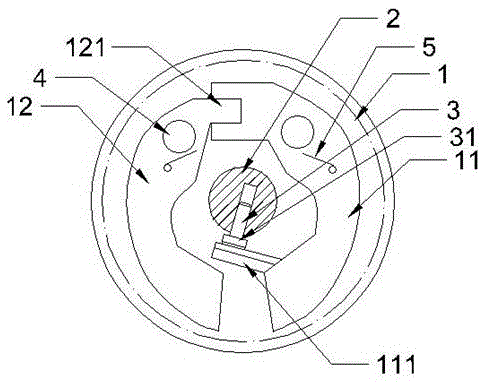
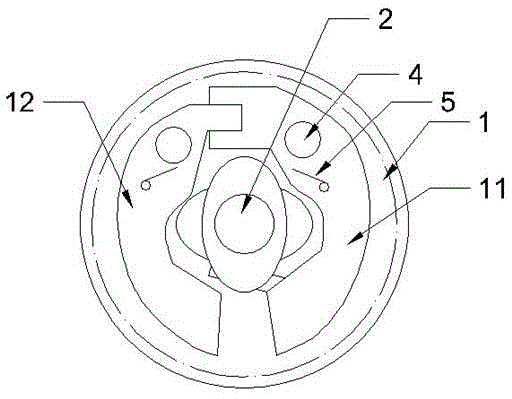
    Figure 2
Patent Text Reader

Abstract

The invention relates to the field of machining, and discloses a diesel engine cam shaft pressure-reducing mechanism. The diesel engine cam shaft pressure-reducing mechanism comprises a cam shaft and a driven gear and multiple cams which are installed on the cam shaft, a first centrifugal arm and a second centrifugal arm are rotatably connected to the driven gear, the first centrifugal arm and the second centrifugal arm are each provided with a reset elastic part, the first centrifugal arm is provided with a driving end and an executing end, an opening is formed in the driving end of the first centrifugal arm, a protruding block which is inserted into the opening is arranged on the second centrifugal arm, mutual linkage of the first centrifugal arm and the second centrifugal arm is achieved, and an executing block is arranged at the executing end of the first centrifugal arm; a pin hole is formed in the cam shaft, a pressure-reducing pin is inserted into the pin hole, and the pin hole is in clearance fit with the pressure-reducing pin. The two centrifugal arms are adopted, under the situation that the rotating speed is the same, the rotating force on the centrifugal arms is larger, and opening is easier, that is to say, the critical speed of rotation is decreased; meanwhile, improvement can be conducted only by adding one centrifugal arm, the technology is simple, and implementation is easy.
Need to check novelty before this filing date? Find Prior Art

Description

technical field

[0001] The invention relates to the field of machining. Background technique

[0002] In order to make the engine start smoothly, it is generally adopted to set a decompression mechanism on the engine to reduce the pressure in the cylinder when the engine starts, so as to ensure the smooth start of the engine.

[0003] The engine camshaft decompression mechanism currently used to reduce the cylinder pressure when the engine starts includes a camshaft on which an exhaust cam and a driven gear are arranged. The side of the driven gear is equipped with a centrifugal device. The driven gear and the exhaust The camshaft section between the cams is milled with a plane groove, and the pressure reducing valve is installed on the plane groove on the camshaft section. The assembly structure of the pressure reducing valve is: the pressure reducing valve is riveted to the plane groove on the camshaft section through a pressure reducing pin Above, the static and displace...

Examples

Embodiment Construction

[0014] The present invention will be described in further detail below by means of specific embodiments:

[0015] The reference numerals in the accompanying drawings include: driven gear 1, first centrifugal arm 11, execution block 111, second centrifugal arm 12, bump 121, camshaft 2, decompression pin 3, cap head 31, rivet 4 , torsion spring 5.

[0016] The embodiment is basically as attached figure 1 with figure 2 Shown: the diesel engine camshaft decompression mechanism in this program includes a camshaft 2, a driven gear 1 and several cams installed on the camshaft 2, and the driven gear 1 is rotatably connected with the first centrifugal arm 11 and The second centrifugal arm 12 is also equipped with a torsion spring 5 .

[0017] The upper end of the first centrifugal arm 11 is processed with an opening, and the second centrifugal arm 12 is processed with a protrusion 121 inserted into the opening so that the first centrifugal arm 11 and the second centrifugal arm 12 a...