
A kind of spiral pipeline cable conveying method

A pipeline cable and cable conveying technology, which is applied in the directions of transportation and packaging, conveying filamentous materials, thin material processing, etc., can solve problems such as low work efficiency, affecting insulation performance, and slow dragging speed, so as to improve conveying efficiency, The effect of prolonging the service life and reducing the conveying resistance

Inactive Publication Date: 2019-07-09
STATE GRID CORP OF CHINA +1
View PDF13 Cites 0 Cited by
  • Summary
  • Abstract
  • Description
  • Claims
  • Application Information

AI Technical Summary

Problems solved by technology

The existing transportation method not only has slow dragging speed, low work efficiency, and often has problems such as insufficient traction force, but also causes damage to the inside of the cable to a certain extent due to strong mechanical pulling, and makes the cable drag in the pipeline, and the tube The friction between the wall and the surface layer of the cable is large, which causes the outer insulation layer of the cable to wear and seriously affects its insulation performance
[0003] After the cable is transported, it is generally blocked and sealed by stuffing sponges, cotton sleeves, etc. into the pipeline. This kind of blocking method is time-consuming and laborious, and the blocking and sealing effects are poor, and the protective effect on the cable after filling is poor.
[0004] Therefore, it is imperative to design a safe, labor-saving and fast cable pipeline transportation method to solve the problem that pipeline cables are difficult to pass through the pipeline

Method used


Image

  • A kind of spiral pipeline cable conveying method
  • A kind of spiral pipeline cable conveying method
  • A kind of spiral pipeline cable conveying method

Examples


Embodiment 1

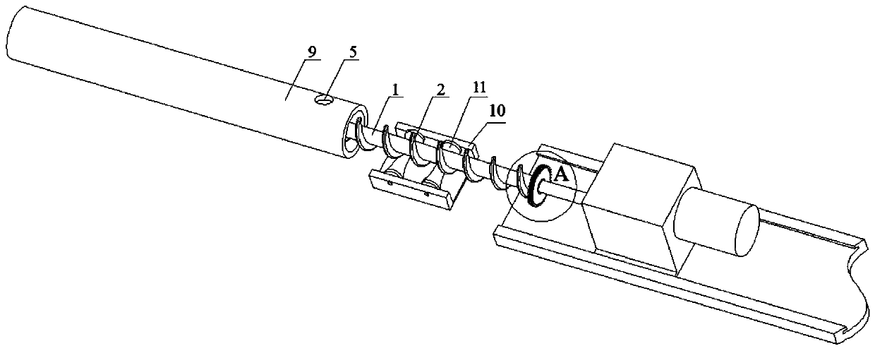
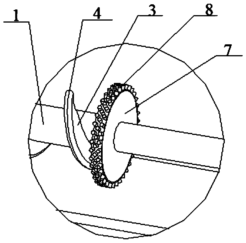
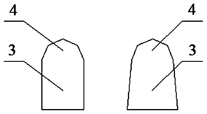
[0047] A spiral pipeline cable conveying method. This method is completed by means of a cable conveying device. The cable conveying device includes a horizontal drilling machine. The cable 1 is fixedly connected to the drill pipe of the horizontal drilling machine. The spiral blade is set and fixed on the cable 1. 2. The spiral blade 2 includes a blade root 3 and a blade tip 4 fixedly connected to the blade root 3. The cross section of the blade tip 4 is circular, and the ratio of the thickness L of the blade root 3 to the diameter D of the blade tip 4 is 1:1 , the ratio of the outer diameter of the spiral blade 2 to the inner diameter of the pipe 9 is 0.8:1, both ends of the spiral blade 2 are discs 7, and the ratio between the diameter of the disc 7 and the inner diameter of the pipe 9 The ratio is 0.8:1, the periphery of the disc 7 is also provided with a brush ring 8, the outer diameter of the brush ring 8 is the same as the inner diameter of the pipeline 9, and the cable 1...

Embodiment 2

[0052] A spiral pipeline cable conveying method. This method is completed by means of a cable conveying device. The cable conveying device includes a horizontal drilling machine. The cable 1 is fixedly connected to the drill pipe of the horizontal drilling machine. The spiral blade is set and fixed on the cable 1. 2. The spiral blade 2 includes a blade root 3 and a blade tip 4 fixedly connected to the blade root 3. The cross section of the blade tip 4 is circular, and the ratio of the thickness L of the blade root 3 to the diameter D of the blade tip 4 is 1:1.1 , the ratio of the outer diameter of the spiral blade 2 to the inner diameter of the pipe 9 is 0.8:1, both ends of the spiral blade 2 are discs 7, and the ratio between the diameter of the disc 7 and the inner diameter of the pipe 9 The ratio is 0.9:1, the periphery of the disc 7 is also provided with a brush ring 8, the outer diameter of the brush ring 8 is the same as the inner diameter of the pipeline 9, and the cable...

Embodiment 3

[0057] A spiral pipeline cable conveying method. This method is completed by means of a cable conveying device. The cable conveying device includes a horizontal drilling machine. The cable 1 is fixedly connected to the drill pipe of the horizontal drilling machine. The spiral blade is set and fixed on the cable 1. 2. The spiral blade 2 includes a blade root 3 and a blade tip 4 fixedly connected to the blade root 3. The cross section of the blade tip 4 is circular, and the ratio of the thickness L of the blade root 3 to the diameter D of the blade tip 4 is 1:1.2 , the ratio of the outer diameter of the spiral blade 2 to the inner diameter of the pipe 9 is 0.8:1, both ends of the spiral blade 2 are discs 7, and the ratio between the diameter of the disc 7 and the inner diameter of the pipe 9 The ratio is 0.9:1, the periphery of the disc 7 is also provided with a brush ring 8, the outer diameter of the brush ring 8 is the same as the inner diameter of the pipeline 9, and the cable...


PUM


Abstract

The invention discloses a spiral pipe cable conveying method, and belongs to the technical field of pipe cables. The spiral pipe cable conveying method is finished by dint of a cable conveying device;the cable conveying device comprises a horizontal drilling machine; a cable is fixedly connected with a drill rod of the horizontal drilling machine; spiral blades sleeve and are fixed on the cable;the spiral blades comprise roots, and tips fixedly connected with the roots; the cross sections of the tips are circular; a ratio of thicknesses L of the roots to diameters D of the tips is 1: (1-1.2); the cable is driven by the horizontal drilling machine to form a spiral pipe cable conveying structure; the cable conveying structure comprises a support frames with a walking mechanism and arrangedbetween the drill rod and a pipe, and a cable groove formed in the support frame; a shaft roller for supporting the cable is arranged in the cable groove; the surface of a roller body of the shaft roller is in an arc groove form; and based on the structure, in the process of spirally conveying the cable to the other end of the pipe by dint of the horizontal drilling machine, blockage particles are finally charged in the pipe. The method can easily, quickly and perfectly convey the cable and the blockage particles in place at the same time.

Description

technical field [0001] The invention belongs to the technical field of pipeline cables, and relates to a spiral pipeline cable conveying method. Background technique [0002] Due to the thick diameter and heavy weight of the pipeline cable, it is very difficult to operate the cable when it is inserted into the pipeline during the laying project of the pipeline cable. At present, the transportation of pipeline cables usually uses a large amount of manpower and large-scale mechanical traction such as winches, tractors, and tractors. The existing transportation method not only has slow dragging speed, low work efficiency, and often has problems such as insufficient traction force, but also causes damage to the inside of the cable to a certain extent due to strong mechanical pulling, and makes the cable drag in the pipeline, and the tube The friction between the wall and the surface layer of the cable is relatively large, which causes the outer insulation layer of the cable to ...

Claims


Application Information

Patent Timeline
Patent Type & Authority Patents(China)
IPC IPC(8): B65H51/02C08L23/16C08L91/00C08K13/02C08K3/22C08K5/09C08K5/00C08K3/00
Inventor 杜明明吴灏何彦强杜洁安少聪许春光曹星马非
Owner STATE GRID CORP OF CHINA
Learn More