Plate type heat exchanger and method of manufacturing heat exchanger

A heat exchanger, flat-plate technology, applied in the field of flat-plate heat exchangers, can solve problems such as poor brazing, damage to flat-plate adhesion, etc., and achieve the effect of improving performance

Inactive Publication Date: 2003-12-24
PANASONIC CORP
View PDF0 Cites 1 Cited by
  • Summary
  • Abstract
  • Description
  • Claims
  • Application Information

AI Technical Summary

Problems solved by technology

When the plates are stacked, if the burrs contact each other, the adhesion between the plates will be greatly damaged, which will easily lead to poor brazing

Method used


Image

  • Plate type heat exchanger and method of manufacturing heat exchanger
  • Plate type heat exchanger and method of manufacturing heat exchanger
  • Plate type heat exchanger and method of manufacturing heat exchanger

Examples


Embodiment Construction

[0030] Embodiments of the present invention will be described below with reference to the accompanying drawings.

[0031] (Embodiment 1)

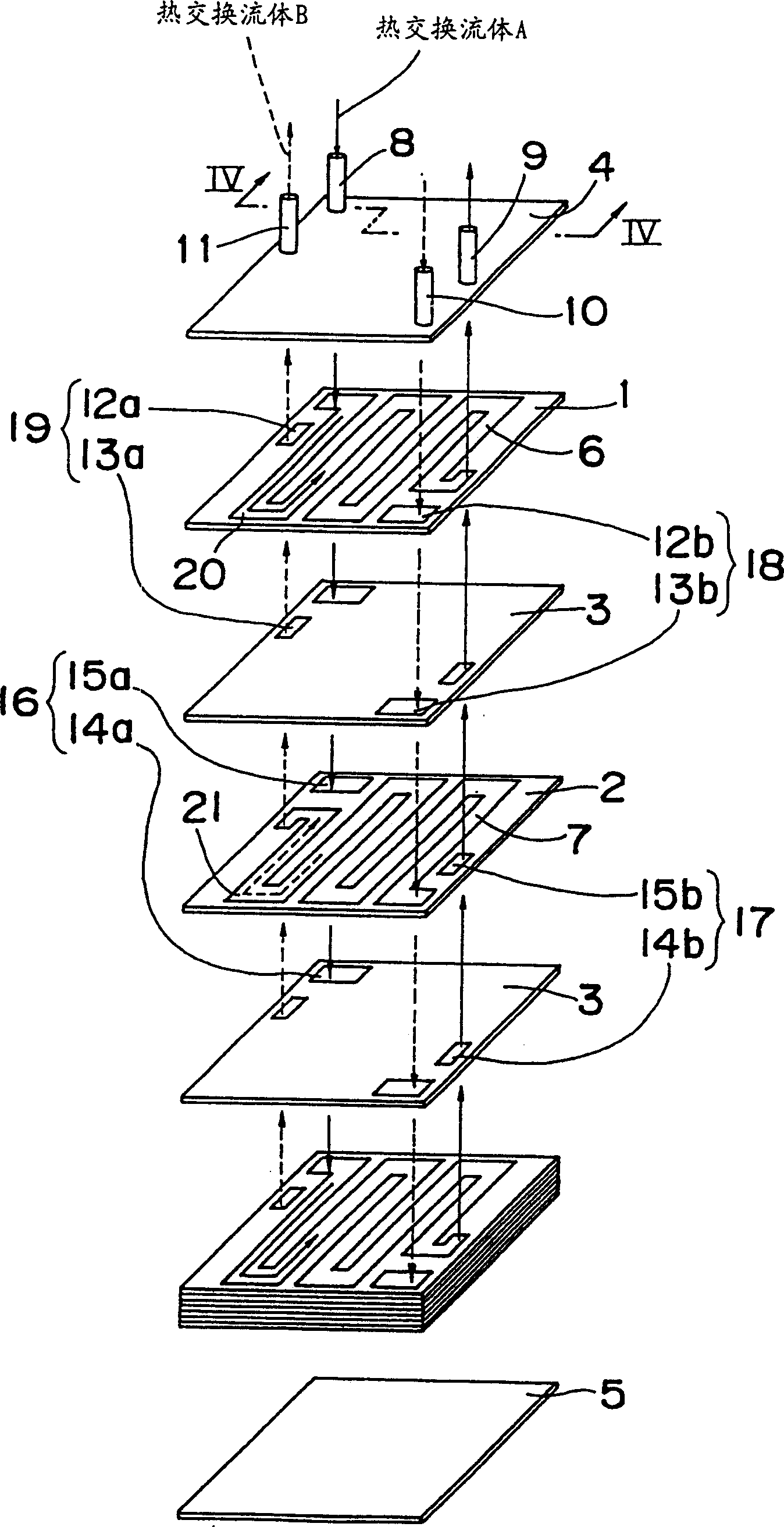
[0032] figure 1 The plate heat exchanger according to Embodiment 1 of the present invention is partially disassembled in the figure to clearly show its internal structure.

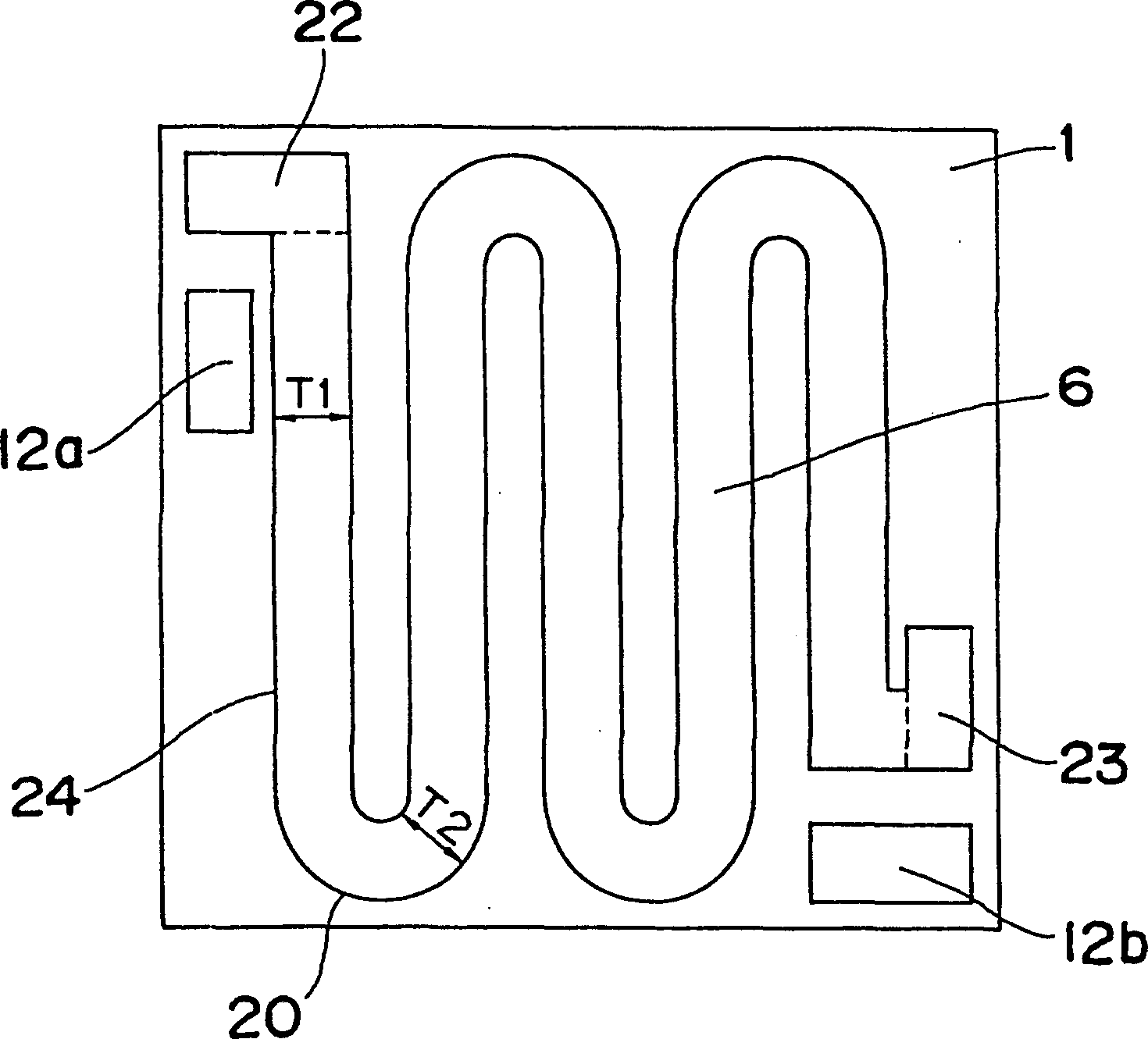
[0033] In this flat plate heat exchanger, a plurality of flat plates are arranged between a pair of end plates, on which a flow channel has been formed through the plate surface, and a plurality of flow channels that are not connected to each other are arranged in the planes of different plates among the plurality of flat plates. The fluids flowing in multiple channels at the same time flow in opposite directions.

[0034] Specifically, as figure 1 As shown, a plurality of flow channel plates 1 and 2 are alternately stacked between a pair of end plates 4 and 5 with a partition plate 3 interposed therebetween. The heat exchanger fluid passing through the plate surfa...


PUM


Abstract

A plate type heat exchanger, wherein a plurality of plates in which flow paths passing through the plate surfaces are formed are disposed between a pair of end plates, a plurality of flow paths not communicating with each other are provided in the plane of the same or different plates among the plurality of plates, and fluids flowing through the plurality of flow paths are so designed as to flow opposedly to each other, whereby an increased performance and reduced size of the plate type heat exchanger can be provided because a plurality of fluids performs heat exchange in the form of a counter flow having high heat transfer characteristics.

Description

technical field [0001] The present invention relates to a flat plate heat exchanger for heat exchange of a liquid as a fluid and a gas-liquid two-phase fluid accompanied by a phase change. Background technique [0002] The plate heat exchanger generally forms a closed flow channel between stacked metal plates, and performs heat exchange on the fluid flowing in the flow channel. This heat exchanger has a larger surface area per unit volume, is more compact, and consumes less material, so it is used to replace the original shell-and-tube heat exchanger. In a general plate heat exchanger, gaskets are used to seal the outer circumference of the plates and the head (ヘツダ—) holes, and each plate is mechanically fixed. The advantage of this heat exchanger is that it can be decomposed and cleaned, but its disadvantage is that the temperature and pressure range of the fluid used is limited. [0003] Aiming at this general flat heat exchanger, Japanese Patent Laid-Open No. 63-137793 ...

Claims


Application Information

Patent Timeline
Patent Type & Authority Patents(China)
IPC IPC(8): B21D53/04F28D9/00F28F3/00F28F3/04F28F13/14
CPCF28D9/0075F28F3/04Y10T29/49393Y10T29/49366F28F2250/102F28D9/00
Inventor 松本聪渡边竹司西山吉继
Owner PANASONIC CORP
Why Eureka
Try Eureka