
Water jet vacuum pump

A water jet vacuum and drain pipe technology, which is applied to jet pumps, pumps, non-displacement pumps, etc., can solve the problem that the extrusion force of the water flow is reduced, the horizontal card is difficult to discharge outward, and the small stones follow the water flow into the vacuum chamber, etc. question

Inactive Publication Date: 2021-08-03
YUHUAN DEGU NEW MATERIAL TECH CO LTD
View PDF0 Cites 1 Cited by
  • Summary
  • Abstract
  • Description
  • Claims
  • Application Information

AI Technical Summary

Problems solved by technology

[0003] Since the water jet vacuum pump extracts the external water flow, if the vacuum pump extracts the river water with many small stones, it is easy to make the small stones follow the water flow into the vacuum chamber. If the small stones are in a long strip state, By entering into the vacuum chamber longitudinally and rotating due to the water flow inside the vacuum chamber, it will be stuck in the inner side of the water outlet and it is difficult to discharge outward, which will cause a decrease in the extrusion force of the water flow.

Method used


Image

  • Water jet vacuum pump
  • Water jet vacuum pump
  • Water jet vacuum pump

Examples


Embodiment 1

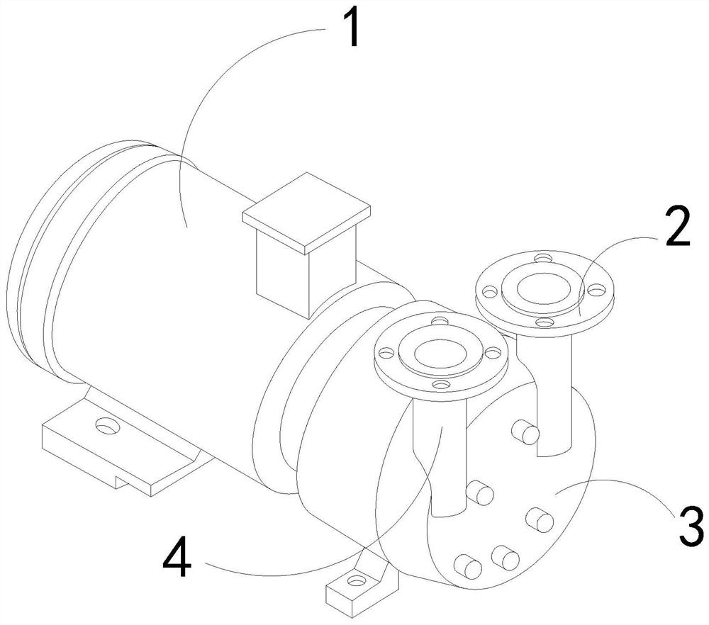
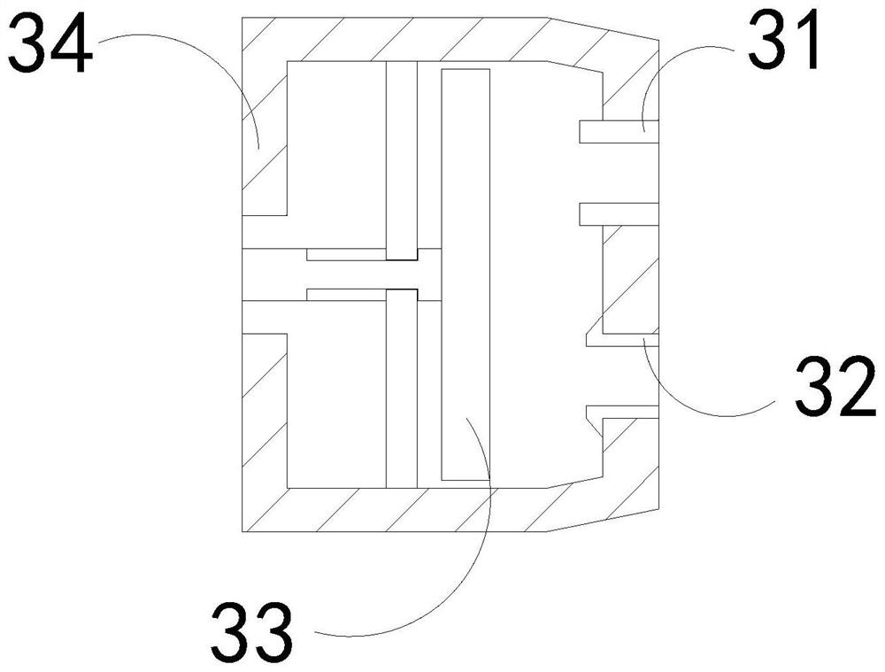
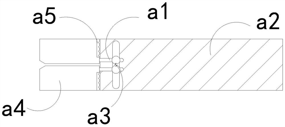
[0026] For example figure 1 -example Figure 5 Shown:

[0027] The invention provides a water jet vacuum pump, the structure of which includes a driving end 1, a drain pipe 2, a booster chamber 3, and a water inlet pipe 4. The drain pipe 2 is embedded in the booster chamber 3, and the water inlet pipe 4 is connected to The pressure chamber 3 is connected, and the pressure chamber 3 is integrated with the driving end 1; the pressure chamber 3 includes a water outlet 31, a water inlet 32, a booster frame 33, and an outer frame 34. The water outlet 31 Through the inner position of the outer frame 34 , the water inlet 32 ​​is embedded in the inner position of the outer frame 34 , and the booster frame 33 is movably engaged with the outer frame 34 .

[0028] Wherein, the water outlet 31 includes a linkage rod a1, a plate surface a2, a pull-back strip a3, a clamping plate a4, and a wear-increasing surface a5. The linkage rod a1 is movably engaged with the plate surface a2, and the...

Embodiment 2

[0034] For example Figure 6 -example Figure 8 Shown:

[0035] Wherein, the breaker bar b3 includes a fixed plate b31, an adsorption block b32, and a swing block b33. The adsorption block b32 is embedded in the inner position of the fixed plate b31, and the swing block b33 is hingedly connected with the fixed plate b31. The swing block There are two b33, and they are evenly distributed symmetrically at the left and right ends of the fixed plate b31. Through the vibration generated by the inward contraction of the mechanism, the swing block b33 can swing down along the fixed plate b31, and the adsorption block b32 adopts permanent magnets Material can generate attraction to the swing block b33 made of metal.

[0036] Wherein, the swing block b33 includes an engaging plate c1, a transition block c2, and an extrapolating block c3, the transition block c2 is movably engaged with the engaging plate c1, and the extrapolating block c3 is installed at the front end of the transitio...


PUM


Abstract

The invention discloses a water jet vacuum pump which structurally comprises a driving end, a drainage pipe, a pressurizing cavity and a water inlet pipe, the drainage pipe is fixedly connected with the pressurizing cavity in an embedded mode, the water inlet pipe is connected with the pressurizing cavity, and the pressurizing cavity and the driving end are of an integrated structure. Through thrust generated by water flow to a clamping plate, a connecting block can be driven by thrust transmitted by the clamping plate to drive a pull-back strip to rotate along a bearing plate, so that the connecting block can drive the clamping plate to rotate, and a crushing rod can extend outwards along a plate body, so that the crushing rod can impact and crush long-strip small stones clamped by the clamping plate, the situation that long-strip-shaped small stones are easily driven by water flow to transversely block the inner side of the water outlet is effectively avoided, through vibration generated by inward shrinkage of the crushing rod, a swing block can swing outwards along a fixing plate, and therefore an outer pushing block can extend outwards under cooperation of a transition block, and the outer pushing block can push and remove small chipping layers outwards.

Description

technical field [0001] The invention relates to the field of vacuum pumps, in particular to a water jet vacuum pump. Background technique [0002] The water jet vacuum pump is mainly used for cross-regional transmission of water flow. By pumping the external water flow into the vacuum chamber, and then pressurizing the water flow through the internal relatively vacuum environment, the water flow can be quickly squeezed out through the water outlet. , and then through the drainage pipe to discharge the water into the external conduit for cross-region transmission, based on the above description, the inventors found that the existing water jet vacuum pump mainly has the following deficiencies, for example: [0003] Since the water jet vacuum pump extracts the external water flow, if the vacuum pump extracts the river water with many small stones, it is easy to make the small stones follow the water flow into the vacuum chamber. If the small stones are in a long strip state, B...

Claims


Application Information

Patent Timeline
IPC IPC(8): F04F5/04F04F5/44F04F5/46
CPCF04F5/04F04F5/44F04F5/46
Inventor 闫保全
Owner YUHUAN DEGU NEW MATERIAL TECH CO LTD
Learn More