Hydraulic machine with hydraulic pressurizing mechanism

A hydraulic press and hydraulic technology are applied to hydraulic presses. It can solve the problems of reduced life, low working speed, and increased height of hydraulic cylinders, and achieve the effects of reduced equipment size, simplified hydraulic system, and large mold opening and closing strokes.

Pending Publication Date: 2021-08-03
HENAN UNIV OF SCI & TECH
View PDF7 Cites 0 Cited by
  • Summary
  • Abstract
  • Description
  • Claims
  • Application Information

AI Technical Summary

Problems solved by technology

Generally, a large-scale hydraulic press is used to solve the problem. For a large-scale hydraulic press with large stroke and high pressure, the main method is to increase the pressure of the hydraulic press by increasing the diameter or quantity of the hydraulic cylinder, and increase the stroke of the hydraulic press by increasing the height of the hydraulic cylinder. , and the large-diameter hydraulic cylinder structure will inevitably result in a large hydraulic machine structure, high price, complex hydraulic system, and low working speed, which greatly increases the production cost.
[0003] Using a conventional pressurization mechanism to pressurize is a common pressurization method for hydraulic mechanisms, but it will greatly increase the height of the hydraulic cylinder, which is helpless for hydraulic presses with large strokes; and for hydraulic presses with pressurization mechanisms, the control pipeline is under The high pressure will reduce its life and the probability of leakage

Method used


Image

  • Hydraulic machine with hydraulic pressurizing mechanism

Examples


Embodiment 1

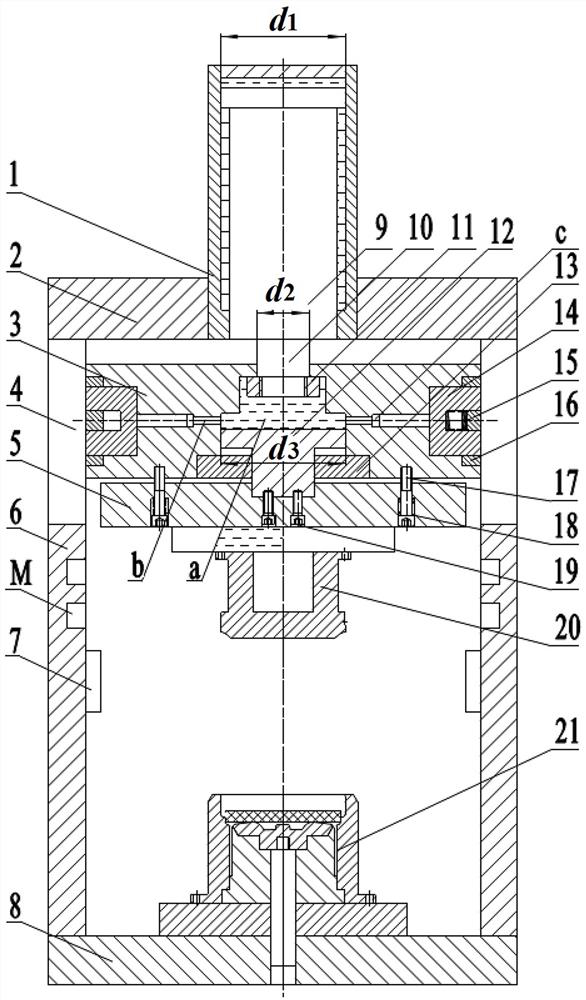
[0032] The specific structure of one of the embodiments of the present invention is described in detail below in conjunction with the accompanying drawings: as figure 1 As shown, a hydraulic press with a hydraulic pressure boosting mechanism includes a main engine and a hydraulic system for controlling the main engine, wherein the main engine includes a main hydraulic cylinder 1, an upper beam 2, a movable beam 3, a lower beam 8, and a column 4, and the movable beam 3 is equipped with a hydraulic booster mechanism, which includes a booster cylinder and a locking mechanism for limiting the position of the booster cylinder body, and also includes a set between the columns 4 on both sides of the hydraulic machine, fixed with the lower beam 8 The connected vertical plate 6 has a pin hole M, which can restrict the movement of the movable crossbeam 3 when used in conjunction with the locking mechanism.

[0033] In this embodiment, a combined hydraulic chamber a is provided inside th...


PUM


Abstract

A hydraulic machine with a hydraulic pressurizing mechanism comprises a main hydraulic cylinder, a pressurizing cylinder and a locking mechanism used for limiting the position of a cylinder body of the pressurizing cylinder, and the main hydraulic cylinder provides a power source; the pressurizing cylinder is driven by power of the main hydraulic cylinder, after the main hydraulic cylinder drives the pressurizing cylinder to move by a certain stroke, the locking mechanism restrains and fixes the position of a cylinder body of the pressurizing cylinder, the power end of the main hydraulic cylinder provides power for the pressurizing cylinder, pressure is transmitted through a pressure transmitting medium in the pressurizing cylinder, power output of the pressurizing cylinder is achieved, and the hydraulic machine generates pressurizing action. By optimizing the structural composition of the pressurizing mechanism, the hydraulic machine can generate large working pressure and has a large rapid mold opening and closing stroke so as to meet the requirement for extrusion forming of large metal parts.

Description

technical field [0001] The invention relates to the technical field of hydraulic forming equipment, in particular to a hydraulic press with a hydraulic boosting mechanism. Background technique [0002] At present, when hydraulic presses are used for precision forming of large metal parts such as extrusion, precision forging, and liquid die forging, a large forming force is often required to meet the requirements of material deformation; at the same time, a large working stroke is required to meet the requirements of opening Modulus space requirements. Generally, a large-scale hydraulic press is used to solve the problem. For a large-scale hydraulic press with large stroke and high pressure, the main method is to increase the pressure of the hydraulic press by increasing the diameter or quantity of the hydraulic cylinder, and increase the stroke of the hydraulic press by increasing the height of the hydraulic cylinder. , and the large-diameter hydraulic cylinder structure wi...

Claims


Application Information

Patent Timeline
Patent Type & Authority Applications(China)
IPC IPC(8): F15B3/00F15B15/14F15B15/26B21C23/00B21J5/02
CPCF15B3/00F15B15/14F15B15/26B21C23/007B21J5/02F15B2015/268
Inventor 杨茜杨永顺
Owner HENAN UNIV OF SCI & TECH
Why Eureka
Try Eureka