
Tolerance optimization method for all-welded assembly

An optimization method, all-welding technology, applied in design optimization/simulation, constraint-based CAD, special data processing applications, etc., can solve problems such as no public reports, application objects, and implementation methods are greatly different, and achieve the realization tolerance. Optimize and improve efficiency

Active Publication Date: 2021-08-03
NUCLEAR POWER INSTITUTE OF CHINA
View PDF10 Cites 4 Cited by
  • Summary
  • Abstract
  • Description
  • Claims
  • Application Information

AI Technical Summary

Benefits of technology

In this patented technology it helps prevent damage caused by excessive heat during manufacturing processes such as laser beam melting or plasma arc cutting. It also optimizes how well parts are designed for use with these techniques based on their ability to resist being bent over time without losing functionality. Overall, this technique allows companies to make better quality products while reducing costs associated therewith.

Problems solved by technology

This patented technical problem addressed in this Patents relates to improving the efficiency and effectiveness of producing parts made up of complicated structures such as power plants or vehicles due to their complexity and variations caused during production. These issues include ensured consistently good quality products despite being subjected to various types of machinery operations like weldings, while minimizing waste and optimum utilities. Current techniques involve trial-and-error approaches based on predefined acceptable ranges and allow only limited adjustment options. There is currently insufficient predictability data available about how well the final component's performance can be affected when used together without causing any significant changes over time.

Method used


Image

  • Tolerance optimization method for all-welded assembly
  • Tolerance optimization method for all-welded assembly

Examples


Embodiment 1

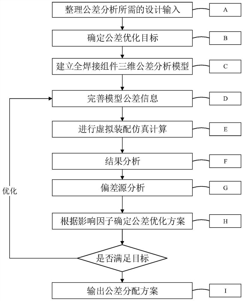
[0033] like figure 1 As shown, the steps are as follows:

[0034] Step A, sort out the design input required for tolerance analysis, specifically including: the component size of the component, design tolerance and other information; the statistical error of the assembly process and fixtures; the statistical results of welding deformation in welding steps obtained from experience ; And focus on the statistics of error sources, control methods and control difficulties of each tolerance.

[0035] Step B, determine the tolerance optimization goal, specifically include: the technical indicators expected to be achieved in the current tolerance optimization, such as the qualified rate of finished product quality requirements through tolerance optimization analysis, and the dimensional requirements to be met in the subsequent process.

[0036] Step C, establishing a three-dimensional tolerance analysis model of the fully welded assembly, specifically includes: establishing a three-dim...

Embodiment 2

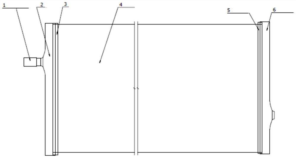
[0045] On the basis of Embodiment 1, the technical characteristics and advantages of this method are described in more detail through an example of tolerance optimization of a large complex structural part.

[0046] A large complex structural part is welded and connected by various components. The quality of the finished product is closely related to the deflection of the joint components. If the deflection is too large, it will directly affect the subsequent processing. Therefore, it is necessary to calculate the cumulative error of the welding deformation of each working step Predict and optimize the tolerance to ensure that the final deflection meets the processing requirements of the subsequent design process.


PUM


Abstract

The invention discloses a tolerance optimization method for all-welded assemblies, relates to welding deformation accumulated error prediction and tolerance optimization of multiple assemblies, and solves the problem of tolerance design optimization requirements of all-welded assemblies. The method comprises the steps that original design information of all-welded assemblies is collected, and various kinds of tolerance information are summarized; a three-dimensional tolerance analysis model is established, simulation analysis is conducted through virtual assembly, and the deviation of the total deflection amount of the all-welded assembly is predicted; and a weighted calculation value is established based on the contribution degree factor and the sensitivity factor of each deviation and the control difficulty factor of welding deformation, and iteration is continuously performed according to a simulation analysis result until a tolerance optimization scheme meeting an optimization target is obtained and output. According to the method, the welding deformation accumulative error can be effectively predicted, tolerance optimization is achieved, and the efficiency of tolerance secondary design is improved.

Description


Claims


Application Information

Patent Timeline
Owner NUCLEAR POWER INSTITUTE OF CHINA
Learn More