
Steam chafing dish energy-gathering cover air pressure valve

A technology of air pressure valve and energy-gathering cover, which is applied to steam cooking utensils, heating devices, cooking utensils, etc., can solve the problems of limited space of the steam table, potential safety hazards, and temperature drop of the steam table, etc., so as to ensure the heat conduction efficiency and improve the Heat utilization effect, heat waste reduction effect

Active Publication Date: 2021-08-06
JIANGSU WOHUIDE INTELLIGENT FLUID TECH CO LTD
View PDF14 Cites 0 Cited by
  • Summary
  • Abstract
  • Description
  • Claims
  • Application Information

AI Technical Summary

Problems solved by technology

[0002] The energy-concentrating cover structure used in the steam hot pot is used to heat water into steam for heating. The space in the steam table is limited. When too much steam enters, the air pressure will rise, which poses a safety hazard. The existing air pressure valve pressure relief structure will Excess steam is discharged to the outside of the steam table, which can stabilize the air pressure in the steam table, but it will cause the temperature inside the steam table to drop and cause a large waste of heat; the steam table directly uses steam to heat the hot pot body, and the liquid attached to the steam The droplet is left on the top of the steam table, which will cause the rising steam to heat the droplet first and then heat the top, and the heat consumption is large, which is insufficient

Method used


Image

  • Steam chafing dish energy-gathering cover air pressure valve
  • Steam chafing dish energy-gathering cover air pressure valve
  • Steam chafing dish energy-gathering cover air pressure valve

Examples


Embodiment Construction

[0033] In order to make the object, technical solution and advantages of the present invention clearer, the present invention will be further described in detail below in combination with specific embodiments and with reference to the accompanying drawings. It should be understood that these descriptions are exemplary only, and are not intended to limit the scope of the present invention. Also, in the following description, descriptions of well-known structures and techniques are omitted to avoid unnecessarily obscuring the concept of the present invention.

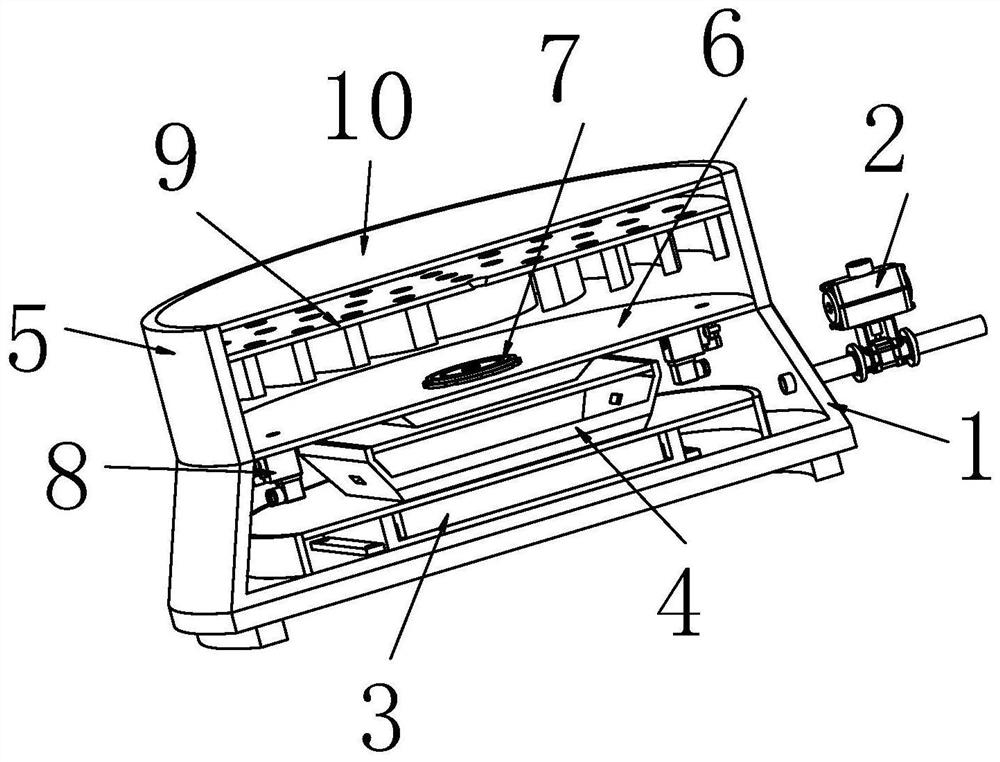
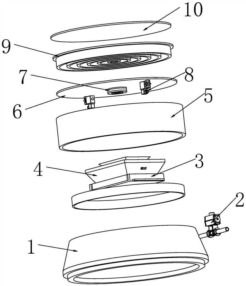
[0034] Such as Figure 1-8 As shown, the connection between the base 1 and the steam table 5 is divided into upper and lower parts by the partition plate 6 as a whole, and the upper part is a steam heating platform, and the steam heating platform is composed of the steam table 5, the partition plate 6 and the heat conduction plate 10 to form an upper seal. The lower part of the cavity is a steam generation platform, and ...


PUM


Abstract

The invention belongs to the field of steam chafing dishes, and particularly relates to a steam chafing dish energy-gathering cover air pressure valve which comprises a base and a steam table, the connecting whole of the base and the steam table is divided into an upper portion and a lower portion through a partition plate, the upper portion is a steam temperature supply platform, and the steam temperature supply platform forms an upper sealing cavity through the steam table, the partition plate and a heat conduction plate. The lower part is a steam generation platform, and the steam generation platform forms a lower sealing cavity through the base and the partition plate; the steam generation platform and the steam temperature supply platform perform gas interaction through a check valve mounted on the partition plate; the steam temperature supply platform and the steam generation platform are communicated through the air pressure valve, redundant steam is discharged for air pressure adjustment, meanwhile, the discharged steam can be used for heating water on the outer side of the energy gathering cover, the heat utilization effect is improved, and heat waste is reduced. And a water-steam separation mechanism can perform water-steam separation on steam, so that water drops are prevented from being attached to the heat conduction plate to cause reduction of the heat conduction effect, and the heat conduction efficiency in the working process is ensured.

Description

technical field [0001] The invention relates to the field of steam chafing dish, in particular to a steam chafing dish energy gathering cover air pressure valve. Background technique [0002] The energy-concentrating cover structure used in the steam hot pot is used to heat water into steam for heating. The space in the steam table is limited. When too much steam enters, the air pressure will rise, which poses a safety hazard. The existing air pressure valve pressure relief structure will Excess steam is discharged to the outside of the steam table, which can stabilize the air pressure in the steam table, but it will cause the temperature inside the steam table to drop and cause a large waste of heat; the steam table directly uses steam to heat the hot pot body, and the liquid attached to the steam Droplets are left on the top of the steam table, which will cause the rising steam to heat the liquid droplets first and then heat the top, and the heat consumption is large, whic...

Claims


Application Information

Patent Timeline
Patent Type & Authority Applications(China)
IPC IPC(8): A47J27/04A47J36/00A47J36/24
CPCA47J27/04A47J36/00A47J36/24A47J2027/043
Inventor 应杰
Owner JIANGSU WOHUIDE INTELLIGENT FLUID TECH CO LTD
Learn More