Production line of steel wire reinforced composite pipe

A technology of enhanced compounding and production line, which is applied in the direction of tubular objects, other household utensils, household utensils, etc. It can solve the problems of tight time when changing discs, core tube deformation, large traction, etc., and achieve high production efficiency, convenient disassembly, speed up and down fast and precise effect

Pending Publication Date: 2021-08-06
ZHANGJIAGANG XIEXIN MACHINERY
View PDF0 Cites 0 Cited by
  • Summary
  • Abstract
  • Description
  • Claims
  • Application Information

AI Technical Summary

Problems solved by technology

[0003] 1. The current steel wire winding requires the use of a steel wire winding machine. During the winding process of the steel wire winding machine, multiple steel wires are released from the pay-off reel. After a certain amount of wire is released, the pay-off reel needs Replacement, and the time for changing the single pay-off reel is relatively tight, and skilled operators are needed to complete it. Therefore, in order to ensure sufficient time for changing the reel, the pulling speed of the entire composite pipe production line should not be too fast; the speed is too fast The speed of winding must also be increased, which affects the worker's changing operation
[0004] 2. When the current wire winding machine pays off, the steel wire is pulled from the pay-off reel and passed through the threading die. During this process, the steel wire needs to change direction and bend more times, which leads to messy wire routing and requires Larger traction force also affects the strength of steel wire;
[0005] 3. During the production process of the current composite pipe, since the core pipe and the formed composite pipe are both drawn and formed horizontally, the core pipe will always have a certain deformation due to the influence of gravity, especially when the core pipe is cooled after forming They are all cooled from the outside to the inside, so the deformation of the inner wall of the core tube is more serious

Method used


Image

  • Production line of steel wire reinforced composite pipe
  • Production line of steel wire reinforced composite pipe
  • Production line of steel wire reinforced composite pipe

Examples


Embodiment Construction

[0037] The present invention will be described in further detail below through specific examples.

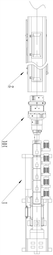
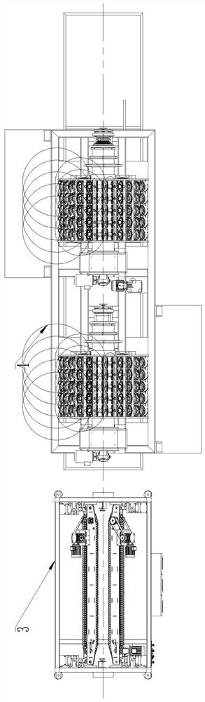
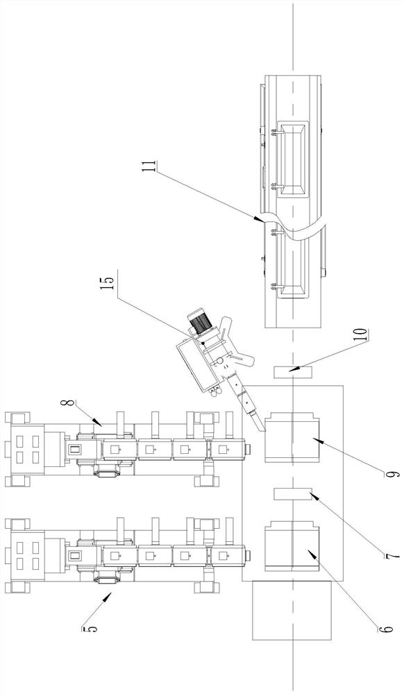
[0038] Such as Figure 1 to Figure 10 As shown, a production line for a steel wire reinforced composite pipe includes a core pipe extruder 1, a core pipe die 101 is provided at the discharge end of the core pipe extruder 1, and a pair of molding pipes is provided downstream of the core pipe die 101. The core tube is cooled by the first cooling box 2, and the downstream of the first cooling box 2 is provided with a first tractor 3, and the first tractor 3 clamps the core tube to provide traction.

[0039] A steel wire winding machine 4 is arranged downstream of the first pulling machine 3, and the steel wire winding machine 4 includes a mounting seat 42 driven by a longitudinal driving device to move longitudinally, and the mounting seat 42 can be slidably installed on the base through a guide rail 41, Of course, if the mounting seat 42 is directly slidably installed on the foun...


PUM


Abstract

The invention discloses a production line of a steel wire reinforced composite pipe. According to the production process of the composite pipe, the production line sequentially comprises a core pipe extruder, a first cooling box, a first traction machine, a steel wire winding machine, a glue layer extruder, a gluing mold, a first cold air ring, a coating mold, an outer layer extruder, a second cold air ring, a second cooling box, a second traction machine and a cutting machine, wherein the steel wire winding machine is driven by a longitudinal driving device to longitudinally slide. By means of the production line, the steel wire winding machine can longitudinally move in the running direction of the pipe in the production process of the composite pipe, so that even if the traction speed of a core pipe is increased, the relative speed between first and second pay-off assemblies and the core pipe is reduced, and enough reel changing time is ensured.

Description

technical field [0001] The invention relates to a production line for steel wire reinforced composite pipes, which belongs to the technical field of production of steel wire composite pipes. Background technique [0002] In the production of steel wire reinforced composite pipe, it is necessary to use a steel wire winding machine to wind steel wire on the outer surface of the core tube of the composite pipe, thereby forming a steel wire reinforcement layer on the outer surface of the core tube, and then coating the outer surface of the steel wire reinforcement layer. The glue is then coated with an outer plastic layer to form a steel mesh reinforced composite pipe. In the production process of composite pipes, there are some disadvantages: [0003] 1. The current steel wire winding requires the use of a steel wire winding machine. During the winding process of the steel wire winding machine, multiple steel wires are released from the pay-off reel. After a certain amount of ...

Claims


Application Information

Patent Timeline
Patent Type & Authority Applications(China)
IPC IPC(8): B29C70/32B29C70/38B29C35/16B29L23/00
CPCB29C35/16B29C70/32B29C70/382B29C2035/1616B29L2023/22
Inventor 陆宇航孙德金
Owner ZHANGJIAGANG XIEXIN MACHINERY
Why Eureka
Try Eureka