Measuring tool storage box for architectural design

A technology for measuring tools and architectural design, applied in tool storage devices, manufacturing tools, containers to prevent mechanical damage, etc., can solve the problems of reducing the efficiency of architectural design and affecting the normal progress of design work, so as to achieve reasonable design and improve the quality of drawing storage , the effect of strong storage capacity

Active Publication Date: 2021-08-06
INNER MONGOLIA UNIV OF TECH
View PDF21 Cites 0 Cited by
  • Summary
  • Abstract
  • Description
  • Claims
  • Application Information

AI Technical Summary

Problems solved by technology

[0003]In the process of architectural design, a large number of design tools need to be used. If they are not effectively classified and stored, a large number of design tools are piled up on the table, which will reduce the efficiency of architectural design and affect the design Therefore, in order to solve this problem, it is urgent to develop a kind of measuring tool storage box for architectural design

Method used


Image

  • Measuring tool storage box for architectural design
  • Measuring tool storage box for architectural design
  • Measuring tool storage box for architectural design

Examples


Embodiment 1

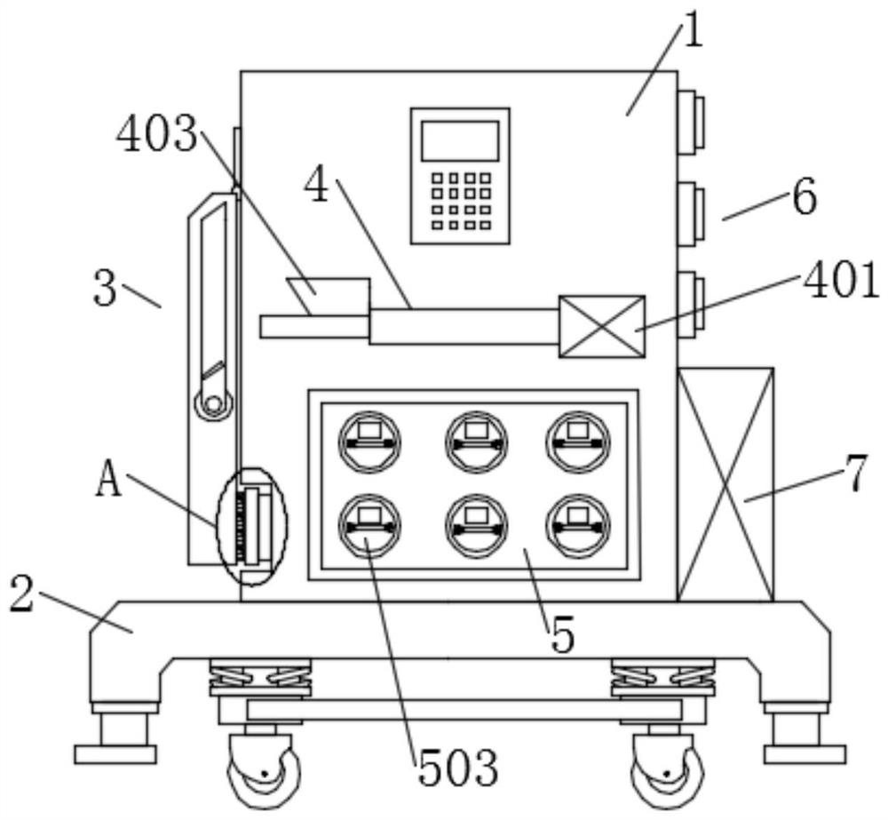
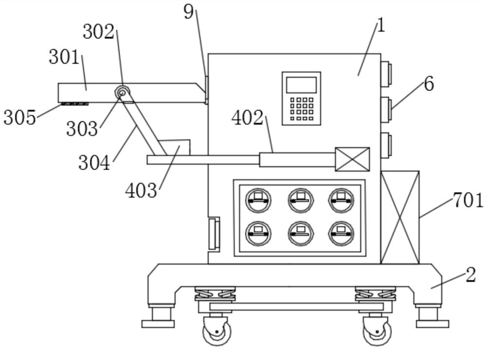
[0024] see Figure 1~5 , in the embodiment of the present invention, a storage box for measuring tools for architectural design, including a box body 1, a load-bearing assembly 2 is installed at the bottom of the box body 1, and the box body 1 can be moved through the load-bearing assembly 2, or can be The assembly 2 is fixedly supported, a movable table assembly 3 is installed on the left side of the outer side of the box body 1, and a connecting hinge 9 for connecting with the movable table assembly 3 is installed on the outer side of the box body 1. The movable table assembly 3 can be The outside of the box body 1 is opened and closed, which is convenient for temporary use. A fixed component 4 is also installed on the front and rear sides of the box body 1 to cooperate with the movable table assembly 3. When the movable table assembly 3 is used, it can cooperate with The two side fixing assemblies 4 fixedly support the middle movable table assembly 3, a drawing storage asse...

Embodiment 2

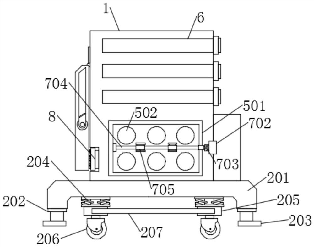
[0026]In this embodiment, the load-bearing assembly 2 includes a load-bearing base 201, four hydraulic telescopic frames 202, four rubber base plates 203, four shock-absorbing connecting frames 204, four universal wheels 205, four connecting seats 206 and Two reinforcing rods 207, the load-bearing base 201 is installed at the bottom of the box 1, the four hydraulic expansion frames 202 are respectively installed at the four corners of the load-bearing base 201, the rubber bottom plate 203 is installed at the bottom of the hydraulic expansion frame 202, and the four shock-absorbing connecting frames 204 are installed at the bottom. The bottom of the load-bearing base 201, the universal wheel 205 is installed on the bottom of the shock-absorbing connecting frame 204 through the connecting seat 206, and the two reinforcing rods 207 are horizontally installed on the outside of the connecting seat 206 on the left and right sides respectively. The hydraulic telescopic frame 202 coope...


PUM


Abstract

The invention discloses a measuring tool storage box for architectural design. The measuring tool storage box comprises a box body, a bearing assembly is installed at the bottom of the box body, a movable table assembly is installed on the left side of the exterior of the box body, and a connecting hinge used for being connected with the movable table assembly is installed on the outer side of the box body; fixing assemblies used in cooperation with the movable table assembly are installed on the front side and the rear side of the box body separately, a drawing storage assembly is installed on the lower portion of the interior of the box body, and a drying device used in cooperation with the drawing storage assembly is further installed on the outer portion of the lower portion of the box body; and three tool storage pull boxes are further installed on the inner upper portion of the box body at equal intervals. The design is reasonable, the storage capacity is high, the movable table assembly is arranged outside, temporary design and practicability are facilitated, the inner drawing storage assembly is matched with the drying device, design drawings can be dried and stored, the drawing storage quality is further improved, and the measuring tool storage box has high practicability and market prospects and is suitable for large-scale popularization and application.

Description

technical field [0001] The invention relates to the tool storage industry, in particular to a measuring tool storage box for architectural design. Background technique [0002] Architectural design means that before the construction of a building, the designer, according to the construction task, makes a comprehensive assumption in advance about the problems that exist or may occur during the construction process and the use process, and formulates the methods and plans to solve these problems. Drawings and documents expressed. As a common basis for material preparation, construction organization and various types of work to cooperate and cooperate in production and construction. It is convenient for the entire project to be carried out smoothly and at a unified pace within the predetermined investment limit and according to the well-considered predetermined plan. And make the completed buildings fully meet the various requirements and uses expected by users and society. ...

Claims


Application Information

Patent Timeline
Patent Type & Authority Applications(China)
IPC IPC(8): B65D25/24B65D25/02B65D81/02B65D25/20B65D81/26B25H3/02
CPCB65D25/24B65D25/02B65D81/02B65D25/20B65D81/266B25H3/02
Inventor 苏晓明郝占国王志强
Owner INNER MONGOLIA UNIV OF TECH
Why Eureka
Try Eureka