High-speed lifting-rotating piece replenishing device
A patch and high-speed technology, which is applied in the field of high-speed lifting-rotating patch devices, can solve the problems of film production speed reduction, achieve the effect of changing efficiency loss and improving production efficiency
- Summary
- Abstract
- Description
- Claims
- Application Information
AI Technical Summary
Problems solved by technology
Method used
Image

Examples
Embodiment Construction
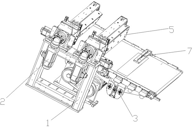
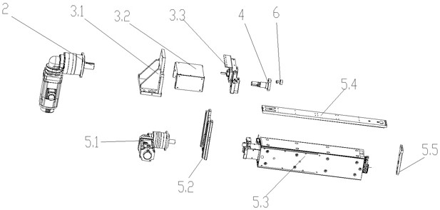
[0017] see figure 1 and figure 2 , the present invention relates to a high-speed lifting-rotating patching device for patching the gaps on the belt conveying line, which includes a patch mounting seat 1 and a plurality of patch assemblies, the patch assembly includes a patch motor 2, Fixing seat assembly 3, eccentric crankshaft 4 and flip assembly 5, the patch motor 2 is fixed on the patch mounting seat 1 through the fixing seat assembly 3, the output end of the patch motor 2 is connected to the eccentric crankshaft 4, the The eccentric crankshaft 4 drives the turning assembly 5 to move up and down. The turning assembly 5 includes a turning motor 5.1, a lifting plate 5.2 and a turning suction cup 5.3. The eccentric crankshaft 4 is connected to the lifting plate 5.2 through a connecting shaft 6, and the lifting plate 5.2 is connected to The shaft 6 is provided with a chute, the turning motor 5.1 is fixed on the lifting plate 5.2, and the output shaft of the turning motor 5.1 ...
PUM
 Abstract
Description
Claims
Application Information