
Longitudinal dual-mode anti-shear protection device for elevator doors

A protection device and dual-mode technology, which is applied in the field of elevator control, can solve the problems of target shear damage, elevator damage, and failure to identify, and achieve the effects of improving detection sensitivity, eliminating vertical detection blind spots, and preventing damage

Active Publication Date: 2021-08-06
山东埃森电梯有限公司
View PDF12 Cites 0 Cited by
  • Summary
  • Abstract
  • Description
  • Claims
  • Application Information

AI Technical Summary

Problems solved by technology

Most manufacturers change the original door machine protection equipment from the safety touch panel to a more sensitive and flexible light curtain device, but due to the contradiction between sensitivity and cost and the inherent defects of optical detection, the light curtain always has certain limitations. Blind areas, for relatively slender targets such as dog leashes or relatively thin transparent objects, there is a risk of not being recognized, and once they are not recognized, it is bound to cause shear damage to the target and also cause damage to the elevator itself , and most of the existing light curtain devices are located on the lateral sides of the elevator door, which increases the probability of missed detection of thin objects

Method used


Image

  • Longitudinal dual-mode anti-shear protection device for elevator doors
  • Longitudinal dual-mode anti-shear protection device for elevator doors
  • Longitudinal dual-mode anti-shear protection device for elevator doors

Examples


Embodiment Construction

[0026] The application will be further described below in conjunction with the accompanying drawings and embodiments.

[0027] It should be noted that the terminology used herein is only for describing specific embodiments, and is not intended to limit the exemplary embodiments according to the present disclosure. As used herein, unless the context clearly dictates otherwise, the singular is intended to include the plural, and it should also be understood that when the terms "comprising" and / or "comprising" are used in this specification, they mean There are features, steps, operations, means, components and / or combinations thereof.

[0028] In this disclosure, terms such as "upper", "lower", "left", "right", "front", "rear", "vertical", "horizontal", "side", "bottom" etc. refer to The orientation or positional relationship is based on the orientation or positional relationship shown in the drawings, and is only a relative term determined for the convenience of describing the...


PUM


Abstract

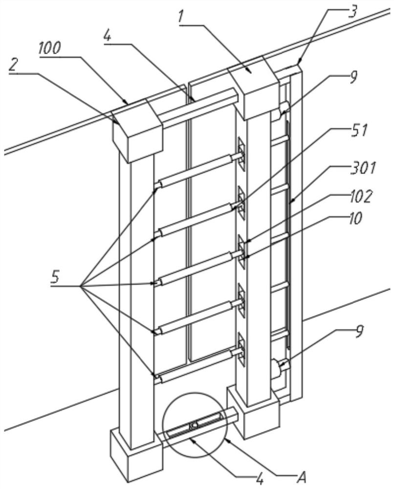
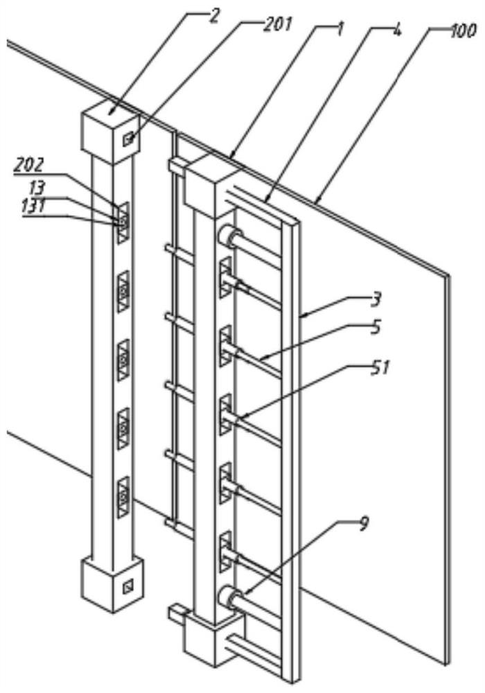
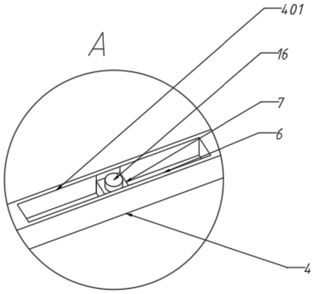
The present application provides a longitudinal dual-mode anti-shear protection device for elevator doors. The longitudinal dual-mode anti-shear protection device comprises a base column and a pin column arranged on two car doors respectively and opposite to each other; a connecting seat is arranged at the side, away from the pin column, of the base column; ejector rods are transversely arranged at the two ends of the base column; a plurality of displacement rods are arranged at the middle part of the base column; the ejector rods and the displacement rods slidably penetrate through the base column, and one end of each ejector rod and one end of each displacement rod are movably connected with the pin column and the other end of each ejector rod and the other end of each ejector rod are fixedly connected to the connecting seat; displacement guide rails are arranged on opposite sides of the two ejector rods; an infrared transmitter and an infrared receiver fitting with each other are arranged on displacement sliding blocks of the displacement guide rails correspondingly; telescopic mechanisms are arranged at the side, away from the pin column, of the base column; output portions of the telescopic mechanisms are connected to the connecting seat; and a pressure-sensitive sensor is arranged on each displacement rod. According to the present application, the detection strength of a door machine protection device is improved through a physical contact mode and an optical non-contact mode in the longitudinal direction of elevator doors, a longitudinal detection blind area can be eliminated conveniently, and the detection sensitivity is further improved.

Description

technical field [0001] The present application relates to the technical field of elevator control, in particular to a longitudinal dual-mode elevator door anti-shear protection device. Background technique [0002] The statements in this section merely provide background technical information relevant to this application and do not necessarily constitute prior art. [0003] With the development of science and technology, the elevator control technology is constantly updated, and the door machine protection equipment is also constantly updated. Most manufacturers change the original door machine protection equipment from the safety touch panel to a more sensitive and flexible light curtain device, but due to the contradiction between sensitivity and cost and the inherent defects of optical detection, the light curtain always has certain limitations. Blind areas, for relatively slender targets such as dog leashes or relatively thin transparent objects, there is a risk of not ...

Claims


Application Information

Patent Timeline
Patent Type & Authority Applications(China)
IPC IPC(8): B66B13/24B66B13/12B66B13/14B66B13/30B66B13/08
CPCB66B13/24B66B13/125B66B13/146B66B13/30B66B13/08
Inventor 李树禹
Owner 山东埃森电梯有限公司
Learn More