Immersion nozzle

A technology of nozzles and protruding parts, which is applied in the direction of manufacturing tools, casting molten material containers, casting equipment, etc., and can solve the problems of large changes in the liquid level in the mold and large changes in the discharge flow of molten steel

Active Publication Date: 2021-08-06
KROSAKI HARIMA CORP
View PDF15 Cites 0 Cited by
  • Summary
  • Abstract
  • Description
  • Claims
  • Application Information

AI Technical Summary

Problems solved by technology

[0007] However, in the case of such a unit that is divided into liquid steel flows in the left and right directions, there is still a change in the flow of molten steel discharge between the left and right discharge holes. large, resulting in a large change in the liquid level in the mold

Method used


Image

  • Immersion nozzle
  • Immersion nozzle
  • Immersion nozzle

Examples


Embodiment A

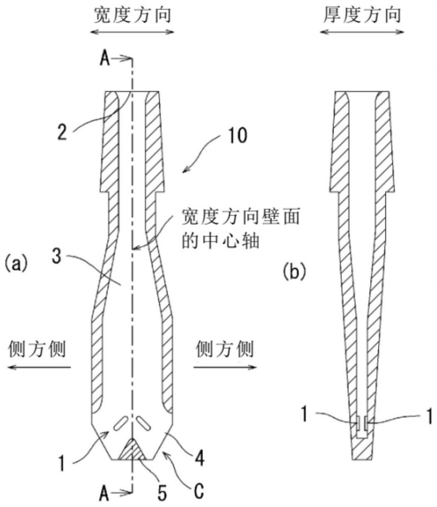
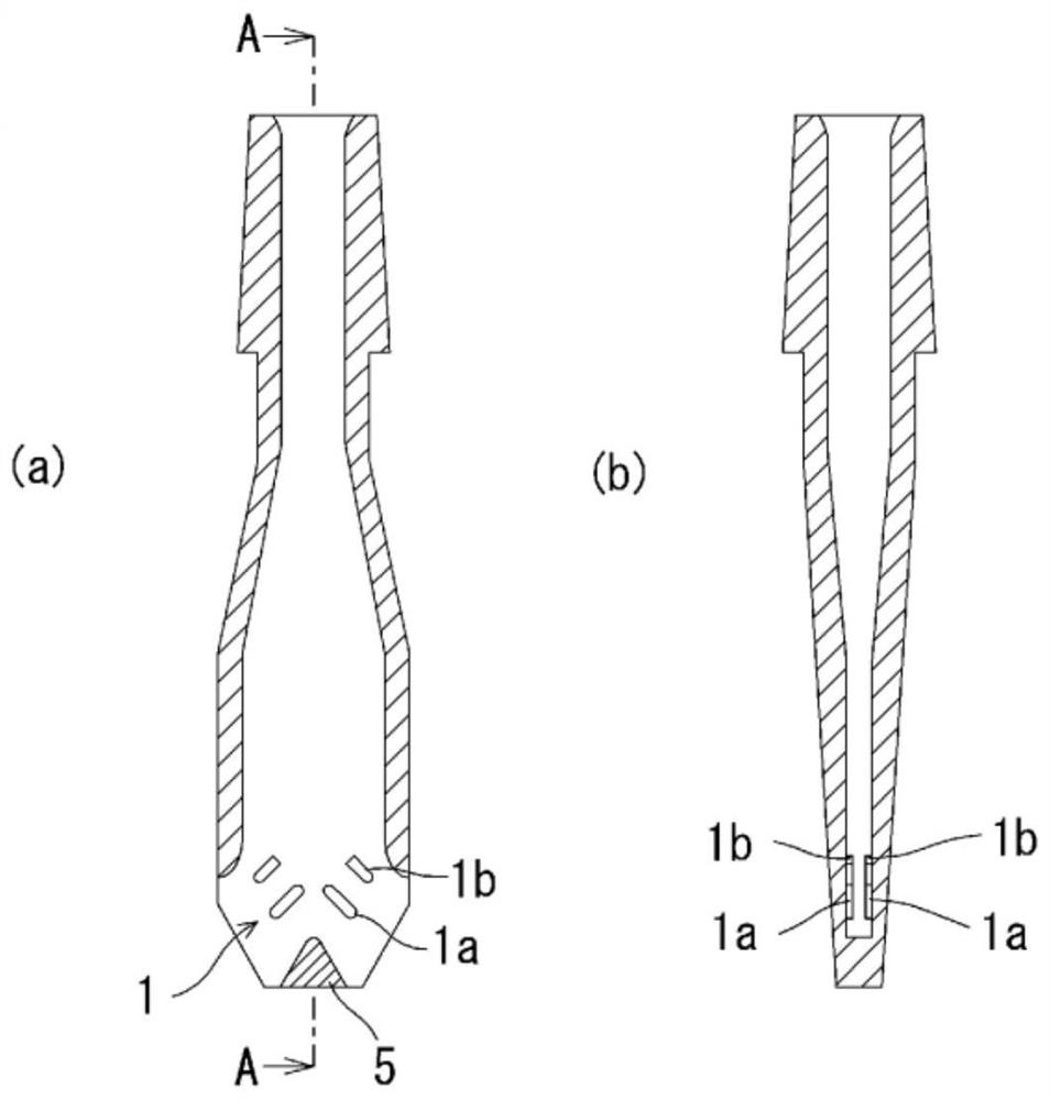
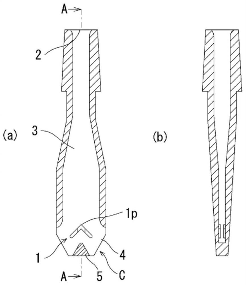
[0077] Embodiment A is water model experiment result, for figure 2 The second aspect of the present invention shown and Figure 4 The submerged nozzle according to the fourth aspect of the present invention shown has the protruding length (total length of a pair of symmetrical protruding parts) Ts, The ratio of Tp to the thickness of the inner hole of the submerged nozzle (length in the short side direction) Tn Ts / Tn, Tp / Tn and the degree of change in the liquid level in the mold (the drift index in the mold and the height of the change in the liquid level in the mold) relationship, the figure 2 The second aspect of the present invention shown is that two layers of axially-symmetrical and plane-symmetrical side protrusions 1a, 1b are provided as protrusions, and no central protrusion is provided between the lower side protrusions 1a, 1a. The shape of the part, the Figure 4 In the fourth aspect of the present invention shown, two layers of axially-symmetrical and plane-sy...

Embodiment B

[0113] Embodiment B is water model experiment result, shows that there is Figure 4 In the fourth form of the present invention shown, the upper end faces of the lower lateral protrusion 1a and the central protrusion 1p are formed as follows: Figure 9 The degree of change in the liquid level in the mold when the shape shown is in the direction of the center of the inner hole and the plane is inclined downward.

[0114] Here, the Ts / Tn ratio of the lower lateral protrusions=0.74, the Tp / Tn ratio of the central protrusions=0.18, and the inclination angle of the lower lateral protrusions and central protrusions toward the inner hole ( Figure 9 The case where θ) is 0 degrees (horizontal) is compared with the case of 45 degrees. Other conditions are identical with embodiment A.

[0115] Figure 19 Show the result. Figure 19 The vertical axis of is the value obtained by averaging the maximum liquid level change values ​​Sw (mm) in the left and right directions of the discharg...


PUM

PropertyMeasurementUnit
lengthaaaaaaaaaa
heightaaaaaaaaaa

Abstract

The objective of the present invention is to stabilize a discharge flow of molten steel and stabilize the melt surface inside a mold, that is, to reduce fluctuation thereof, in a flat immersion nozzle. In the present invention, lateral protrusion parts 1 protruding in the thickness direction are provided in the wall surface in the width direction of a flat portion in an immersion nozzle, which has a flat shape in which the width Wn of an inner hole is greater than the thickness Tn of the inner hole. These lateral protrusion parts 1 are arranged so as to form a pair slanting in the width direction and downward, at axisymmetric positions with respect to center axis in the vertical direction of the wall surface in the width direction, and the lateral protrusion parts 1 are arranged facing each other in both wall surfaces in the width direction.

Description

technical field [0001] The present invention relates to an immersion nozzle for continuous casting for pouring molten steel from a tundish into a mold, and more particularly to an immersion nozzle near the discharge hole of the immersion nozzle if it is used for a thin plate, a medium plate, etc. The transverse (perpendicular to the vertical direction) section is a flat submerged nozzle. Background technique [0002] In the continuous casting process of continuously cooling and solidifying molten steel to form cast slabs of a predetermined shape, the continuous casting immersion nozzle (hereinafter simply referred to as "immersion nozzle") installed on the bottom of the tundish injects the Molten steel is poured inside. [0003] Generally, the dipping nozzle is composed of a pipe body whose upper end is an inlet for molten steel, inside which is formed a molten steel flow path (inner hole) extending downward from the molten steel inlet and has a bottom, and On the lower si...

Claims


Application Information

Patent Timeline
Patent Type & Authority Applications(China)
IPC IPC(8): B22D11/10B22D41/50
CPCB22D41/50B22D11/10B22D11/0408
Inventor 福永新一香月和久矢野顺也古川大树
Owner KROSAKI HARIMA CORP
Why Eureka
Try Eureka