Method and apparatus for continuous casting of metals

A continuous casting and metal technology, applied in the field of continuous casting of metals and its devices, can solve problems such as segregation of molten metal, large molten metal, increased flow rate of molten metal, etc.

Inactive Publication Date: 2006-05-10
JFE STEEL CORP
View PDF1 Cites 4 Cited by
  • Summary
  • Abstract
  • Description
  • Claims
  • Application Information

AI Technical Summary

Problems solved by technology

[0004] But, there is following problem in this method: when using static magnetic field to carry out braking (electromagnetic braking) to molten metal flow, molten metal is easy to produce segregation on stagnation position; When stirring (electromagnetic stirring) molten metal with moving magnetic field, Flux is easily entangled

Method used


Image

  • Method and apparatus for continuous casting of metals
  • Method and apparatus for continuous casting of metals
  • Method and apparatus for continuous casting of metals

Examples


Embodiment

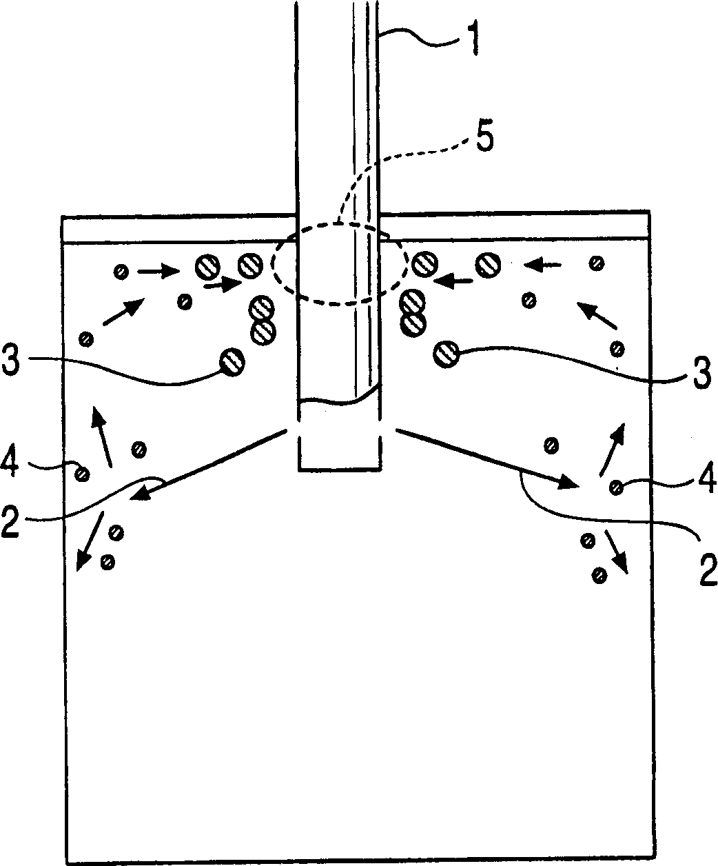
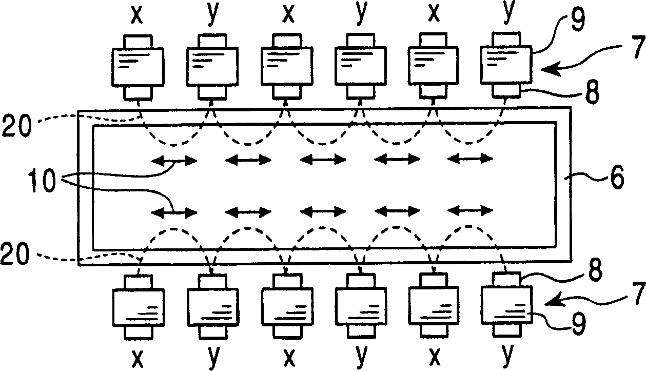
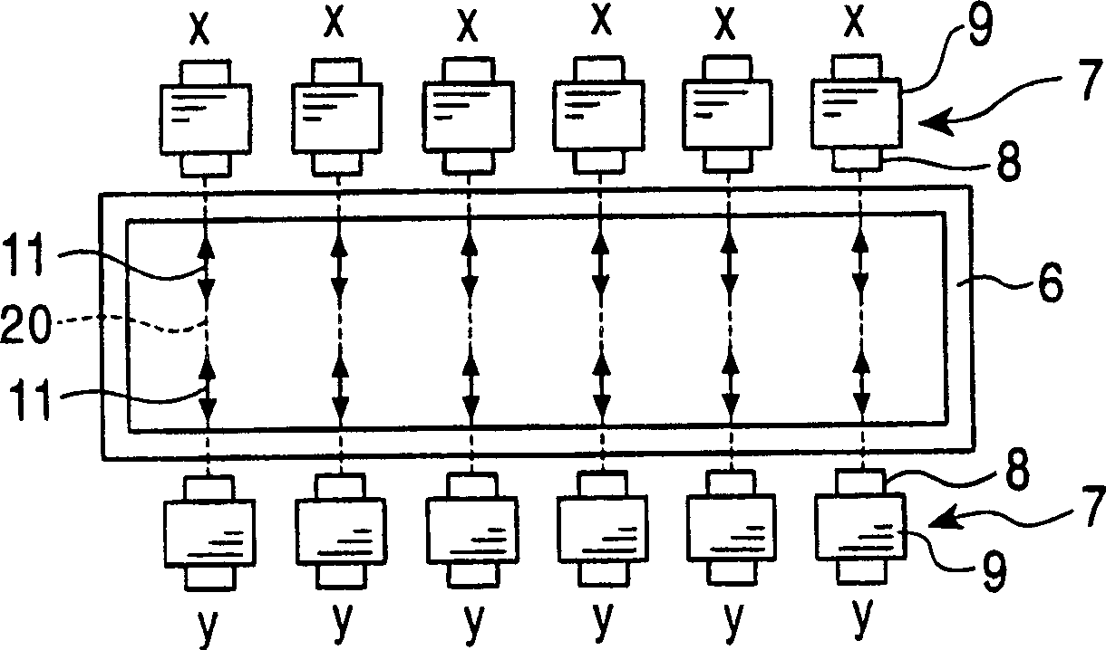
[0056] Through the continuous casting machine, using the dipping nozzle, at the pouring speed of 4-5t / min, about 300t of ultra-low carbon aluminum-killed steel smelted by the converter-RH treatment process (the representative chemical composition is shown in Table 1) is poured into the mold When pouring, when casting a continuous casting slab with a width of 1500-1700mm and a thickness of 220mm, the figure 2 , image 3 , Figure 4 In any of the forms, the electromagnet is arranged on the position including the position corresponding to the surface of the molten metal in the mold, and the coils of the electromagnet are passed with three-phase alternating current or single-phase alternating current of various frequencies. Continuous casting experiments were carried out with a moving magnetic field with a maximum flux density of 0.1T, or three-phase, or a non-moving vibrating magnetic field, or no external magnetic field.

[0057] In this experiment, three items of surface seg...


PUM


Abstract

Provided is a metal continuous casting method in which continuous casting is performed while applying a static magnetic field in the thickness direction of the continuous casting, by intermittently applying the above static magnetic field, it is possible to obtain substantially no auxiliary Continuous casting slab with flux entrainment and surface segregation.

Description

[0001] This application is a divisional application, the application number of the parent application is 00128484.3, the application date of the parent application is November 17, 2000, and the invention name of the parent application is a continuous casting method and device for metal. technical field [0002] The invention relates to a continuous casting method and device for controlling the flow of molten steel by using a magnetic field in the continuous casting process of steel. Background technique [0003] In the continuous casting process, when the liquid metal (metal liquid) is poured into the mold, the dipping nozzle is often used. In this case, if the flow velocity on the surface of the molten metal is too high, the flux on the upper part of the molten metal will be involved; if the flow velocity on the surface of the molten metal is too small, the molten metal will tend to stagnate at its position and cause segregation. Finally, surface segregation is formed. The...

Claims


Application Information

Patent Timeline
IPC IPC(8): B22D11/115B22D11/04B22D11/11
Inventor 山根浩志别所永康三木祐司竹内秀次桐原理
Owner JFE STEEL CORP
Why Eureka
Try Eureka